


SPYDER® BACNET® PROGRAMMABLE CONTROLLERS
21 63-2689—05
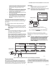
2. Once the terminal block is raised 1/4 in. (6.35 mm) from
its alignment pins, grasp the terminal block at its center
(for long terminal blocks grasp it at each end) and pull it
straight up.
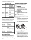
Controller Replacement (PVB0000AS,
PVB4022AS and PVB6436AS)
For PVB0000AS, PVB4022AS and PVB6436AS controllers,
which are hard-wired to an actuator, perform the following
actions to replace the complete assembly (controller and
actuator):
1. Remove all power from the controller.
2. Remove the two air flow pickup connections from the
pressure sensor.
3. Remove the terminal blocks (See “Terminal Block
Removal” ).
4. Remove the old controller and actuator assembly from its
mounting.
• Loosen the two bolts on the actuator clamp to release
the actuator from the shaft.
• Remove the controller’s mounting screws.
• Gently pull the controller and actuator assembly
straight out, until the assembly is clear of the actuator
shaft.
5. Mount the new controller and actuator assembly (See
“Installation” on page 3.).
6. Reconnect the two air flow pickup tubes to the pressure
sensor (See “Piping (PVB0000AS, PVB4022AS,
PVB4024NS, PVB6436AS and PVB6438NS)” on
page 6.).
7. Replace the terminal blocks:
• Insert each terminal block onto its alignment pins.
• Press straight down to firmly seat it.
• Repeat for each terminal block.
8. Restore power to the controller.
9. Perform “Checkout” on page 19.
Controller Replacement (PVB4024NS
and PVB6438NS)
Perform the following to replace the PVB4024NS and
PVB6438NS controllers:
1. Remove all power from the controller.
2. Remove the two air flow pickup connections from the
pressure sensor.
3. Remove the terminal blocks.
• See “Terminal Block Removal” on page 20..
4. Remove the old controller from its mounting.
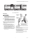
IMPORTANT
(FOR CONTROLLERS MOUNTED TO A DIN RAIL):
1. Push straight up from the bottom to release the top
pins.
2. Rotate the top of the controller outwards to release
the bottom flex connectors (see Fig. 8 on page 6).
5. Mount the new controller.
• See “Installation” on page 3.
6. Reconnect the two air flow pickup tubes to the pressure
sensor (See “Piping (PVB0000AS, PVB4022AS,
PVB4024NS, PVB6436AS and PVB6438NS)” on
page 6.).
7. Replace the terminal blocks:
• Insert each terminal block onto its alignment pins.
• Press straight down to firmly seat it.
• Repeat for each terminal block.
8. Restore power to the controller.
9. Perform “Checkout” on page 19.
Controller Replacement (PUB1012S,
PUB4024S, and PUB6438S)
Perform the following to replace the PUB1012S, PUB4024S
and PUB6438S controllers:
1. Remove all power from the controller.
2. Remove the terminal blocks (See “Terminal Block
Removal” on page 20.).
3. Remove the old controller from its mounting.
IMPORTANT
(FOR CONTROLLERS MOUNTED TO A DIN RAIL):
1. Push straight up from the bottom to release the top
pins.
2. Rotate the top of the controller outwards to release
the bottom flex connectors (see Fig. 8 on page 6).
4. Mount the new controller (See “Installation” on page 3.).
5. Replace the terminal blocks:
• Insert each terminal block onto its alignment pins.
• Press straight down to firmly seat it.
• Repeat for each terminal block.
6. Restore power to the controller.
7. Perform “Checkout” on page 19.