


SPYDER® BACNET® PROGRAMMABLE CONTROLLERS
7 63-2689—05
The application engineer must review the control job
requirements. This includes the sequences of operation for the
controller, and for the system as a whole. Usually, there are
variables that must be passed between the controller and other
Spyder BACnet controller(s) that are required for optimum
system wide operation. Typical examples are the TOD, Occ/
Unocc signal, the outdoor air temperature, the demand limit
control signal, and the smoke control mode signal.
It is important to understand these interrelationships early in
the job engineering process, to ensure proper implementation
when configuring the controllers. Refer to the controller
Application Guides.
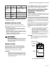
Power Budget
A power budget must be calculated for each device to
determine the required transformer size for proper operation. A
power budget is simply the summing of the maximum power
draw ratings (in VA) of all the devices to be controlled. This
includes the controller itself and any devices powered from the
controller, such as equipment actuators (ML6161 or other
motors) and various contactors and transducers.
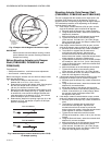
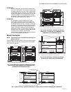
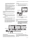
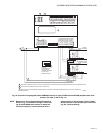
IMPORTANT
• When multiple controllers operate from a single
transformer, connect the same side of the transformer
secondary to the same power input terminal in each
device. The earth ground terminal (terminal 3) must
be connected to a verified earth ground for each
controller in the group (see Fig. 12 on page 9).
• Half-wave devices and full-wave devices must not use
the same AC transformer. If a Spyder controller will
share its power supply with another device, make
sure the other device utilizes a half-wave rectifier and
that the polarity of the wiring is maintained.
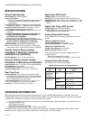
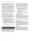
POWER BUDGET CALCULATION EXAMPLE
Table 3 is an example of a power budget calculation for a
typical PVB6436AS controller. While the example is shown for
only this model, the process is applicable for all controller
models.
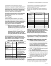
Table 3. Power budget calculation example.
The system example above requires 30.7 VA of peak power.
Therefore, a 100 VA AT92A transformer could be used to
power one controller of this type. Because the total peak power
is less than 33 VA, this same transformer could be used to
power three of these controllers and meet NEC Class 2
restrictions (no greater than 100 VA).
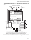
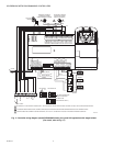
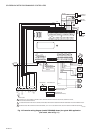
See Fig. 11–Fig. 12 beginning on page 9 for illustrations of
controller power wiring. See Table 4 for VA ratings of various
devices.
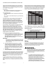
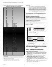
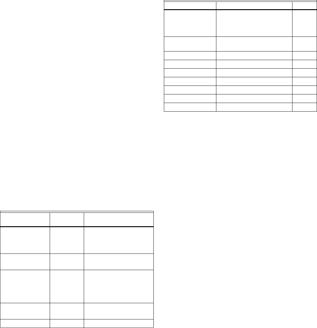
Table 4. VA ratings for transformer sizing.
For contactors and similar devices, the in-rush power ratings
should be used as the worst case values when performing
power budget calculations. Also, the application engineer must
consider the possible combinations of simultaneously
energized outputs and calculate the VA ratings accordingly.
The worst case, which uses the largest possible VA load,
should be determined when sizing the transformer.
Each controller requires 24 Vac power from an energy-limited
Class II power source. To conform to Class II restrictions (U.S.
only), transformers must not be larger than 100 VA. A single
transformer can power more than one controller.
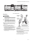
GUIDELINES FOR POWER WIRING ARE AS FOLLOWS:
— For multiple controllers operating from a single
transformer, the same side of the transformer
secondary must be connected to the same power input
terminal in each device. The earth ground terminal
must be connected to a verified earth ground for each
controller in the group (see Fig. 12 on page 9).
Controller configurations are not necessarily limited to
three devices, but the total power draw, including
accessories, cannot exceed 100 VA when powered by
the same transformer (U.S. only).
— See Fig. 11 on page 9 for controller power wiring used
in UL 1995 equipment (U.S. only).
— Many controllers require all loads to be powered by the
same transformer that powers the controller.
— Keep the earth ground connection wire run as short as
possible (refer to Fig. 11–Fig. 12 beginning on page 9).
— Do not connect earth ground to the controller’s digital or
analog ground terminals (refer to Fig. 11 and Fig. 12).
— Unswitched 24 Vac power wiring can be run in the
same conduit as the L
ONWORKS® Bus cable.
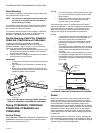
Line-Loss
Controllers must receive a minimum supply voltage of 20 Vac.
If long power or output wire runs are required, a voltage drop
due to Ohms Law (I x R) line-loss must be considered. This
line-loss can result in a significant increase in total power
Device
VA
Information
Obtained From
PVB6436AS
controllers (include
Series 60 Floating
Damper Actuator)
9.0 See “Specifications” on
page 2.
R8242A Contactor
fan rating
21.0
TRADELINE
®
Catalog
inrush rating
D/X Stages 0.0 For example, assume
cooling stage outputs are
wired into a compressor
control circuit and have no
impact on the budget.
M6410A Steam
Heating Coil Valve
0.7
TRADELINE
®
Catalog,
0.32A 24 Vac
TOTAL 30.7
Device Description VA
PVB6436AS
controllers and
Series 60 Floating
Damper Actuator
Controller and Actuator 9.0
PUB6438S or
PVB6438NS
Controller 5.0
ML684 Versadrive Valve Actuator 12.0
ML6161 Damper Actuator, 35 lb-in. 2.2
ML6185 Damper Actuator SR 50 lb-in 12.0
ML6464 Damper Actuator, 66 lb-in. 3.0
ML6474 Damper Actuator, 132 lb-in. 3.0
R6410A Valve Actuator 0.7
R8242A Contactor 21.0