


T775U SERIES 2000 ELECTRONIC STAND-ALONE CONTROLLER
11 62-0255—09
Humidity, Pressure, and Universal
Sensor Calibration
A calibration parameter is available using Setup mode.
The calibration range is +/- 10% of the Min Value to Max
Value range setup for the sensor. See examples in
Table 3.
The calibration value is set in section “1.2.2.3.
CALIBRATE (Sensor A or B)” on page 17.
Temperature Sensor Calibration
As wire length increases, resistance increases and thus
the temperature reading increases. If necessary, calibrate
the sensor input by reducing the value by the amount
shown in the Table 4 on page 11. For example, a wire run
with 18 gauge wire of 1,000 feet, requires a calibration
offset of -6.0°F.
IMPORTANT
If the calibration value in the table exceeds the
controller’s calibration limits of +/-10°F (+/-6°C),
you must use a heavier gauge wire.
For example, with a wire run of 1,000 feet you
must use 20 AWG wire or heavier in order to cal-
ibrate for wire loss within the limits of the control-
ler.
See “1.2.2.3. CALIBRATE (Sensor A or B)” on page 17 for
the instructions to enter the calibration value.
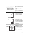
NOTE: The resistance output on the temperature
sensors change at the rate of 2.2 Ohms per
°F (3.85 Ohms per °C).
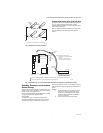
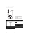
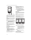
Fig. 20 shows how sensor resistance varies with
temperature for a sensor having a positive temperature
coefficient (PTC) of 2.1 Ohms per degree F (3.85 Ohms
per degree C).
Fig. 20. Sensor Resistance vs. Temperature.
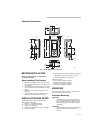
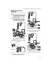
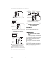
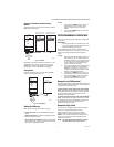
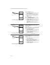
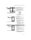
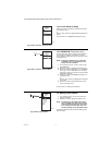
INTERFACE OVERVIEW
The T775U controller uses an LCD panel and 6-button
keypad to provide status information and permit user input
of the programming, setup, and scheduling parameters.
The following figure describes the display areas of the
LCD and the keypad.
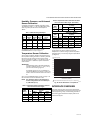
Table 3. Calibration Range Examples.
Units
Min.
Value
Example
Max.
Value
Example
Min-Max
Range
Result
Calibration
Range
PSI 100 400 300 ± 30 PSI
Inches
W.C.
-20.0 20.0 40 ± 4 in. W.C.
Pa or
kPa
-2,000 3000 5000 ± 500 Pa/kPa
% 10 100 90 ± 9%
Table 4. Temperature Sensor Calibration for Resis-
tance Loss due to Wire Length.
AWG
Rating m/ft
Temperature Offset in
°F (Feet)
a
200 ft 500 ft 1,000 ft
14 2.5 0.46 1.14 2.28
16 4.0 0.72 1.82 3.64
18 6.4 1.16 2.90 5.82
20 10.2 1.86 4.64 9.28
22 16.1 2.92 7.32 14.64
AWG
Rating m/m
Temperature Offset in
°C (Meter)
a
100 m 200 m 300 m
14 8.3 0.44 0.86 1.30
16 13.2 0.68 1.38 2.06
18 21.0 1.10 2.18 3.28
20 33.5 1.74 3.48 5.22
22 52.8 2.74 5.48 8.22
a
This is the distance from the controller to the sensor
(already accounts for round trip distance).
Table 4. Temperature Sensor Calibration for Resis-
tance Loss due to Wire Length. (Continued)
AWG
Rating m/ft
Temperature Offset in
°F (Feet)
a
200 ft 500 ft 1,000 ft
M24304
TEMPERATURE (DEGREES)
RESISTANCE (OHMS)
1403
1317
1231
1145
1059
973
20 40 60 80 100 120 140 160 180 200 220
0 10 20 30 40 50 60 70 80 90 100
°F
°C
0-20-40
120
110
250
-40 -20 -10-30
1489
887
801
1097 ± 0.08 OHMS
AT 77°F (25°C)
POSITIVE TEMPERATURE COEFFICIENT (PTC) OF 2.1 OHMS PER °F
1
1