


T775U SERIES 2000 ELECTRONIC STAND-ALONE CONTROLLER
29 62-0255—09
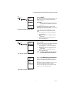
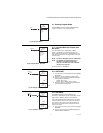
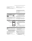
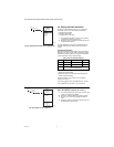
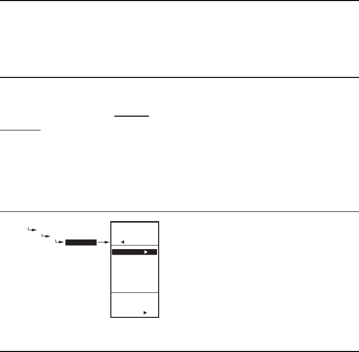
2.2. Program Next Output (Modulating
Output or Relay)
For the next output, select the desired MOD or Relay from
the Program menu (see Fig. 58 on page 27).
Go to “2.1.2. SETPOINT” on page 27 to continue
programming.
When you finish programming the outputs, continue with
“1.3. Exit Programming without Reset”.
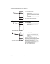
1.3. Exit Programming without Reset
Press the HOME button to leave programming mode and
return to the home screen.
This completes the programming procedure for controllers
that do not use Reset.
3. PROGRAMMING OUTPUTS
(MOD AND RELAY) WITH
RESET
The T775U can be programmed for Reset or No Reset for
each output. From the factory, the T775U is programmed
for No Reset. This section describes the steps necessary
to program the controller for Reset.
To use the Reset feature, the first output (MOD 1) must be
set to Reset=YES in Setup mode (see “3.1. Setting Up the
Controller for Reset”).
NOTE: Even if the MOD outputs are not used, both
MOD 1 and MOD 2 must be set to Reset in
order to configure Reset for the relay(s).
The reset curve established when programming the first
output (MOD 1) is then used for all subsequent outputs
that are configured for Reset, and each of those outputs
will be offset from this curve.
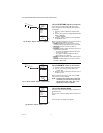
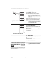
For all outputs that will follow a reset curve, be sure to
configure for Reset=YES in the setup mode. Choose
Reset YES or NO for all other outputs you wish to reset,
then press the HOME button to record your selection.
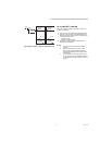
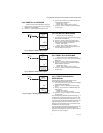
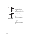
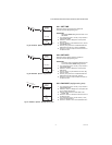
Fig. 65. Reset Setup.
NOTE: The first output, Mod 1, must be set for Reset
to enable the controller’s Reset function.
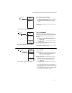
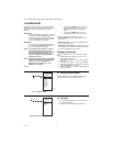
3.1. Setting Up the Controller for Reset
1. Press and hold the MENU button for five seconds to
enter Setup mode.
2. Then choose:
OUTPUTS u
MOD1 u
RESET u
then select YES-BOILER or YES-OTHER (Fig. 65).
You can now press the HOME button to exit Setup mode
and continue with “Determining and Setting the Reset
Values”.
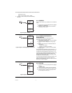
Determining and Setting the Reset
Values
NOTE: When using the Reset feature, Sensor A must
be sensing the controlled temperature (e.g.
Boiler), Sensor B must be sensing the reset-
ting temperature (e.g. outdoor temp).
To program an output for Reset, refer to the values as
shown in the examples below. Choose your own
appropriate values for Sensor A maximum and minimum
and Sensor B maximum and minimum.
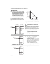
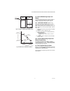
Reset Example: (see Fig. 66)
• Sensor A is the boiler sensor and Sensor B is the
outdoor sensor.
• Maximum boiler temperature desired is 210°F when
the outdoor temperature is 20°F.
• Minimum boiler temperature desired is 160°F when the
outdoor temperature is 70°F.
• With the above settings example, when the outdoor
temperature is 50°F, the effective setpoint is 180°F.
Setback (optional) Example: (see Fig. 66)
• Setback of -10°F is used to drop the temperature at
night by 10°F.
• With the above settings example, when the outdoor
temperature is 50°F, the effective setback setpoint is
170°F (180°F setpoint minus the 10°F setback).
NOTE: A single reset curve is programmed for the
MOD 1 output and is used by all outputs
setup with RESET=YES.
SETUP
OUTPUTS
MOD 1
RESET
SETUP
OUTPUTS
MOD 1
RESET
USE RESET
FOR
MOD 1
YES-BOILER
YES-OTHER
NO
M24568