


T775U SERIES 2000 ELECTRONIC STAND-ALONE CONTROLLER
5 62-0255—09
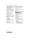
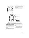
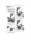
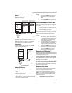
Fig. 3. Parallel-series wiring of sensors.
Temperature Sensor Wire Type and Size
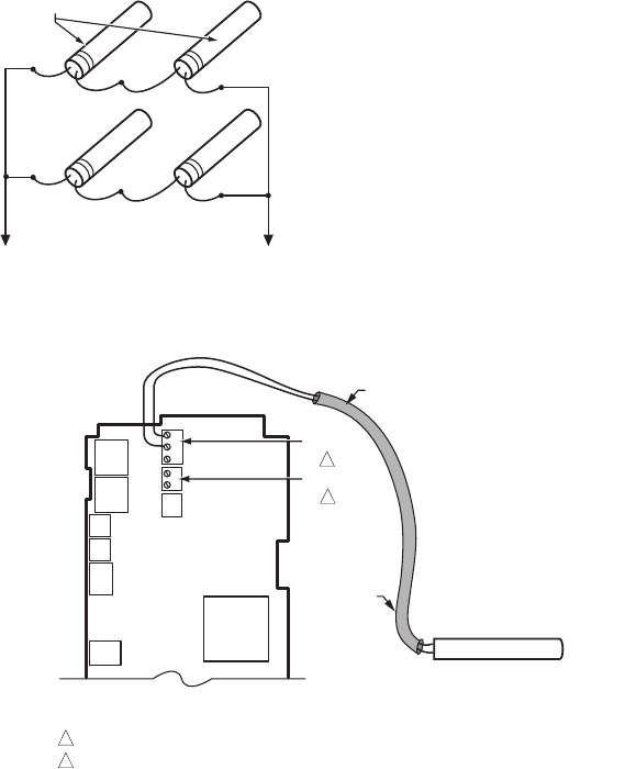
Temperature sensors use standard AWG 18/2 unshielded
wire. For cable runs greater than 25 feet or where
electrical interference may be a problem, shielded cable is
recommended. See Fig. 4.
Refer to “Temperature Sensor Calibration” on page 11 for
wire size selection where cable runs are longer than
25 feet.
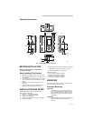
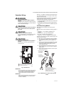
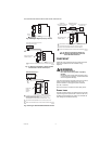
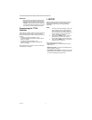
Fig. 4. Sensor Wiring — 2-wire shielded cable connection from Sensor A to temperature sensor.
Humidity, Pressure, and Universal
Sensor Wiring
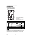
Sensors with a 0-5 Vdc, 0-10Vdc or 4-20mA input to the
T775U must be wired to the Sensor A terminal. Sensor B
is used only as a temperature input.
Sensors use standard AWG 18 unshielded wire. For cable
runs greater than 25 feet, shielded cable is
recommended.
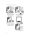
The sensors in Fig. 5 – 8 beginning on page 6 are
examples and illustrate voltage and current wiring for 3-
wire and 2-wire sensors to the Sensor A terminal. For
terminal wiring details, see Fig. 11 and Table 2 on page 8.
Other sensors are supported. See sensor descriptions on
page 2.
NOTES:
1. Other transmitters can be wired in the same
manner. For example, the 0-10Vdc wiring
shown in Fig. 5 on page 6 with the H76XX
sensor can also be done with the P7640 or
any other transmitter.
2. The T775U V terminal outputs 18 Vdc.
TO T775 CONNECTIONS (SENSOR A) OR (SENSOR B).
SENSORS
M24548
M24549A
SENSORS A AND B ARE POLARITY INSENSITIVE WHEN USING A 1097 OHM PTC TEMPERATURE SENSOR.
SENSOR B IS USED ONLY IN RESET APPLICATIONS ON THE T775U20006.
1
SHIELDED
CABLE
SHIELDED
CABLE
SENSOR
NOTE: SHIELDED CABLE MUST BE
CONNECTED TO A SEPARATE EARTH
GROUND.
HOWEVER, DO NOT GROUND
SHIELDED CABLE AT SENSOR END.
NOTE: TO MINIMIZE NOISE PICKUP,
MAKE SENSOR CONNECTION FROM
SHIELDED CABLE AS CLOSE AS
POSSIBLE TO SENSOR BODY.
T
T
T
T
SENSOR A
SENSOR B
1
2
2