


T775U SERIES 2000 ELECTRONIC STAND-ALONE CONTROLLER
62-0255—09 4
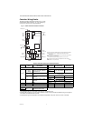
Use a screwdriver to pry out only the knockouts that you
will use.
If mounting on DIN rail, be sure to remove the knockouts
before mounting. See “Controller Wiring” on page 7 and
Fig. 12 on page 9 for recommended knockout usage and
locations. If you do not use an opened knockout be sure
to cover it.
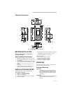
Mount the controller on any convenient interior location
using the four mounting holes provided on the back of the
enclosure using #6 or #8 screws (screws are not provided
and must be obtained separately). Use controller
dimensions in Fig. 1 on page 3 as a guide.
The controller may be mounted in any orientation.
However, mounting in the orientation shown in Fig. 1 on
page 3 permits proper viewing of the LCD display and use
of the keypad.
Humidity, Pressure, and Universal
Sensor(s) Mounting and Location
These sensors may be mounted on a wall or panel. Follow
the installation instructions specific to the sensor you are
installing.
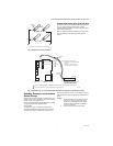
Temperature Sensor(s) Mounting
and Location
Temperature sensors may be located up to 1,000 feet
(304 m) from the T775U controller. See Table 4 on
page 11 for calibration guidelines.
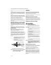
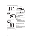
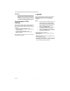
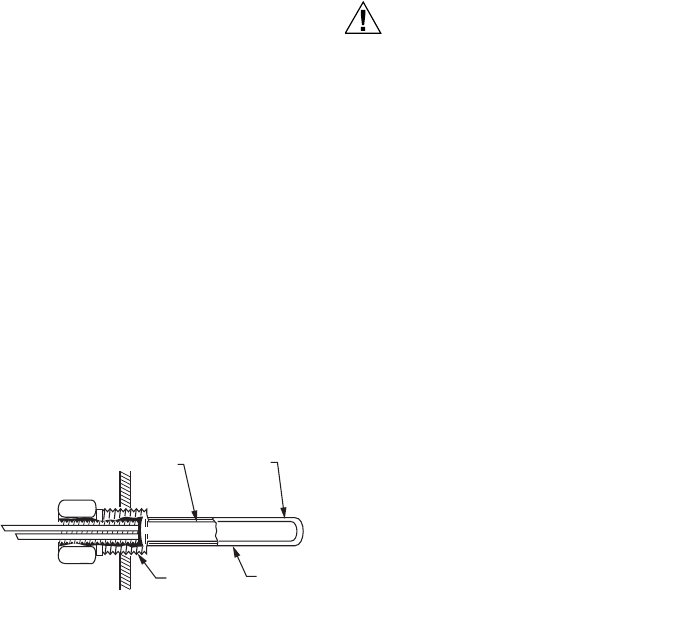
The sensors may be mounted on a wall or panel for
sensing space temperature, strapped to a pipe or inserted
in an immersion well (see Fig. 2) for hot or cold water
sensing, or taped to a standard cap or bulb holder for duct
air sensing. To prevent moisture or condensation entering
the sensor through the lead wire holes, mount the sensor
with the lead wires exiting the bottom of the sensor.
NOTES:
1. The included sensor is not designed for very
wet applications. For immersion applications,
an immersion well is used.
2. Heat conductive compound must be used in
immersion wells.
3. See “Temperature Sensors (Sensor A or B)”
on page 2 for this type of installation.
Fig. 2. Sensor inserted in immersion well.
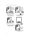
NOTE: Multiple sensors may be parallel-series wired
to sense average temperatures in large
spaces. See Fig. 3 on page 5.
WIRING
All wiring must comply with applicable electrical codes
and ordinances, or as specified on installation wiring
diagrams. Controller wiring is terminated to the screw
terminal blocks located inside the device.
The remainder of this section describes the sensor wiring
and the T775U controller wiring.
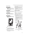
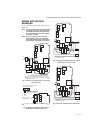
Wiring Connections Access
To access the wiring connections, remove the two screws
on the left side of the enclosure and gently swing open the
top. Be careful to not stress the ribbon cables that connect
the keypad and LCD display to the controller circuit board.
Temperature Sensor Wiring
CAUTION
Electrical Shock Hazard.
Can short equipment circuitry.
Make sure that metal tube of sensor does not
short against T terminals in wall-mounted case.
IMPORTANT
Poor wiring practices can cause erratic readings
from the sensor. Avoid the following to ensure
proper operation:
• Do not route the temperature sensor wiring with
building power wiring.
• Do not locate the temperature sensor wiring next
to control contactors.
• Do not locate the temperature sensor wiring near
electrical motors.
• Do not locate the temperature sensor wiring near
welding equipment.
• Make sure good mechanical connections are
made to both the sensor and the controller.
• Do not mount the sensor with the lead wire end
pointing up in an area where condensation can
occur.
If any of the above conditions cannot be avoided,
use shielded cable.
NOTE: Each T775 controller must be wired to its own
sensor(s). However, a benefit of the T775
controller’s accuracy is that there is no more
than a 2°F differential between any two T775
controllers.
Reset Temperature Control
If you are implementing two-sensor reset control, Sensor
A must always be the controlled temperature and Sensor
B must always be the controlling temperature.
For example, in a reset control based on outside
temperature, Sensor A must be the inside sensor and
Sensor B must be the outside sensor.
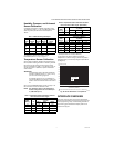
Multiple Parallel Temperature Sensors
Multiple sensors can be parallel-series wired to sense
average temperatures in large spaces. To maintain control
accuracy, the number of sensors to be parallel-series
wired must be of the n
2
power (for example, 4, 9, 16, etc.).
See Fig. 3.
SENSOR
PLACED
IN WELL
IMMERSION
WELL
1/2 NPT
USE HEAT
CONDUCTIVE
COMPOUND
M24379