


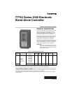
T775U SERIES 2000 ELECTRONIC STAND-ALONE CONTROLLER
62-0255—09 8
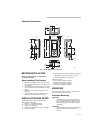
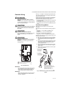
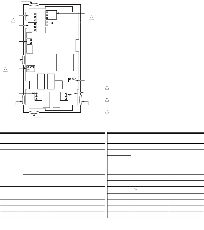
Controller Wiring Details
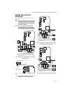
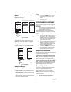
The wiring connection terminals are shown in Fig. 11 and
are described in Table 2. See Fig. 12 – Fig. 19 beginning
on page 9 for typical T775U wiring applications.
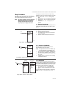
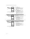
Fig. 11. T775U Terminal and Feature Locations.
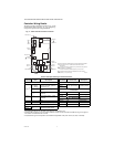
Table 2. Description of Wiring Terminal Connections.
Connection
Terminal
Label Description Connection Terminal Label Description
Sensors Outputs
Sensor A
a
a
For applications that do not use Reset, only Sensor A is available for use.
C – common
S – signal
V – voltage
0-10 Vdc input: Universal
sensor for humidity, pressure,
temperature, etc.
Mod 1
+ - (Vdc or mA)
W R B (Series 90)
b
b
For Series 90 connections, you must insert a 340 Ohm resistor across terminals R and W. See Fig. 18 on page 10.
The resistor is included with the controller.
Modulating Output
Mod 2
S and V 4-20mA input; see Fig. 7 on
page 6 24 Vac Power
T T
Temperature Sensor; polarity
insensitive
24V + + 24 Vac Hot
Common - 24 Vac Common
Sensor B T T Temperature Sensor; polarity
insensitive
Ground
Earth Ground
c
c
A separate earth ground is required for all installations regardless of the power source (24, 120, or 240 Vac).
120 or 240 Vac Power
Input 120 Vac 120 120 Vac Power
DI + - Digital Input (dry contact) Common COM Common
Outputs 240 Vac 240 240 Vac Power
Relay 1 NO / COM /
NC 120-240 Vac Relay Output
Relay 2
C
NO
NC
C
NO
NC
T
T
B
R
W
+
–
+
–
B
R
W
+
–
SENSOR A
SENSOR B
MOD 2
MOD 1
KNOCKOUT A
DIGITAL
INPUT
POWER
120/240 VAC
OUTPUT
RELAY 2
KNOCKOUT D
POWER
24 VAC
OUTPUT
RELAY 1
KNOCKOUT C
KNOCKOUT E
WHEN USED FOR TEMPERATURE OR 4-20mA SENSING, SENSORS A
AND B USE THE TWO TT CONNECTIONS AND ARE POLARITY
INSENSITIVE.
FOR MOD 1 AND MOD 2 CURRENT (mA) OR VOLTAGE (VDC) OUTPUT,
USE SIGNAL (+) & COMMON (-).
FOR MOD 1 AND MOD 2 SERIES 90 OUTPUT, USE W, R, & B.
A SEPARATE EARTH GROUND IS REQUIRED FOR ANY POWER
SOURCE (24, 120, OR 240 VAC)
1
2
1
2
M24553A
KNOCKOUT B
3
3
C
S
V
T
T
–
+
C
+
120
COM
240