


63
English
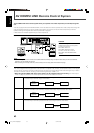
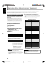
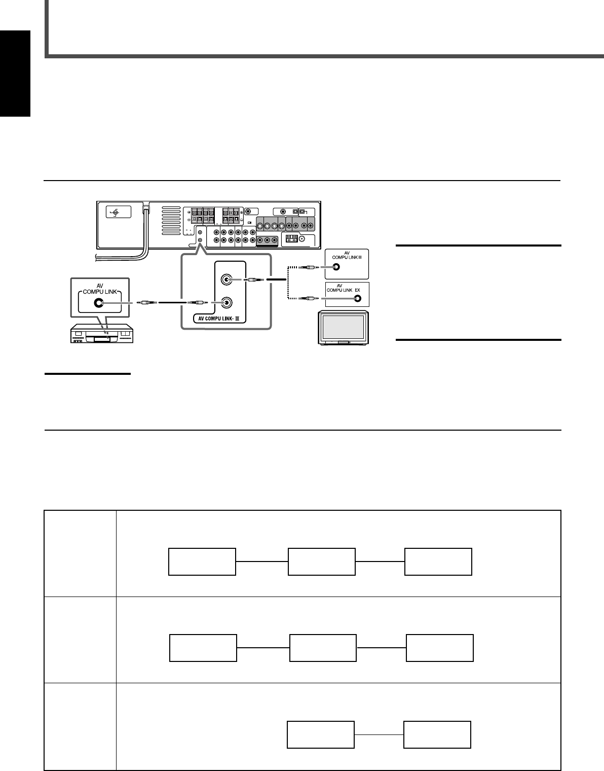
The AV COMPU LINK remote control system allows you to operate JVC’s video components (TV and VCR) through the
unit.
This unit is equipped with the AV COMPU LINK-III, which has added a function to operate JVC’s video components through the
video components terminals. To use this remote control system, you need to connect the video components you want to
operate, following the diagrams below and the procedures on page 64.
• Refer also to the manuals supplied with your video components.
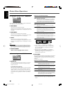
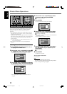
CONNECTIONS 1: AV COMPU LINK Connection
CAUTION:
When connecting the TV with the AV
COMPU LINK remote control system,
connect the unit to the
AV COMPU LINK III or
AV COMPU LINK EX terminal.
DO NOT connect the unit to the
AV COMPU LINK RECEIVER/AMP
terminal.
To Video Input 1
TV
RX-DV31SL
S-video cable
S-video cable
Source
Equipment
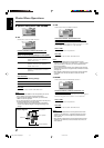
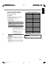
To Video Input 2
Composite
video cable
Composite
video cable
TV
RX-DV31SL
Source
Equipment
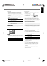
To Video Input 2
Component
video cable
TV
RX-DV31SL
Notes:
• When connecting the unit and a TV with the AV COMPU LINK EX terminal by using a component video cable, you cannot use Automatic
Selection of TV’s Input Mode (see page 64).
• When connecting the VCR only to this unit, connect it directly to the unit using cables with monaural mini-plugs.
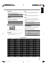
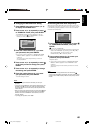
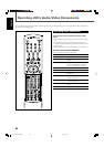
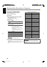
CONNECTIONS 2: Video Cable Connection
This unit is equipped with three types of the video terminals—composite video, S-video, and component video, and the signals
coming into this unit through one type of video terminals can output only through the terminal of the same type. So you need to
connect the VCR and TV to this unit using one of the following two ways—CASE 1 or 2:
• When using the AV COMPU LINK remote control system, set the component video input correctly (see “Video output
mode” on page 27); otherwise, the correct input for this unit will not be selected on the TV.
CASE 1 When connecting the source equipment to the unit through the S-video terminals, connect this unit to the
TV’s Video Input 1 terminal using S-video cables.
CASE 2 When connecting the source equipment to the unit through the composite video terminals, connect this
unit to the TV’s Video Input 2 terminal (composite video input) using composite video cables.
CASE 3 When setting the video output mode of the built-in DVD player to “component,” connect this unit to the
TV’s Video Input 2 terminals (component video input) using component video cables.
AV COMPU LINK Remote Control System
VCR TV
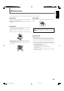
CAUTION:
SPEAKER
IMPEDANCE
1 OR 2:
16 32
816
CAUTION:
SPEAKER
IMPEDANCE
816
1 AND 2:
VOLTAGE
SELECTOR
110V
127V
230-240V
220V
63-74_RX-DV31SL[UW]f.p65 03.4.22, 18:5863