


Filename [DVM700ER_05Name.fm]
Masterpage:Left0
16 EN
Page 16 Wednesday, 20 September 2006 10:03
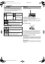
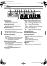
INSTALLING YOUR NEW UNIT
It’s essential that your unit be properly connected.
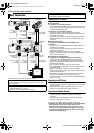
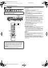
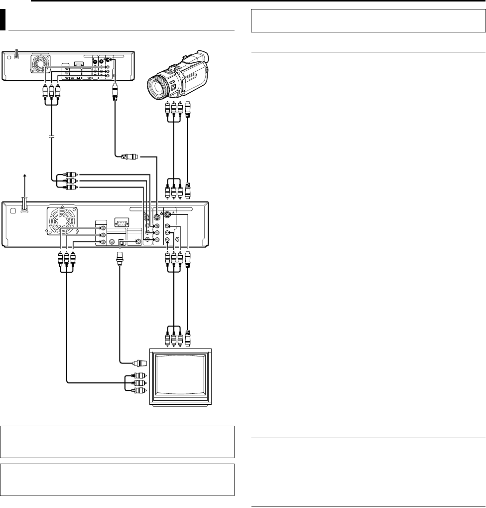
Connecting to a TV Monitor
Connect the unit to a TV depending on the TV and cables you use.
8 AV Connection
To connect to a TV with AV connector ^
A Connect the [AUDIO/VIDEO OUTPUT] connectors on the rear
panel of the unit and the TV’s audio/video input connectors with
the supplied Audio/Video cable.
To connect to a TV with BNC connector ^
A Connect an optional audio cable between the [AUDIO
OUTPUT] connectors on the rear panel of the unit and the TV’s
audio input connectors.
B Connect an optional BNC video cable between the unit’s BNC
[VIDEO OUTPUT] connector and the TV’s BNC VIDEO input
connector.
8 S-Video Connection
To connect to TV’s S-VIDEO input and AUDIO input
connectors ^
A Connect the unit’s [S-VIDEO OUTPUT] connector to the TV’s
S-VIDEO input connector.
B Connect the unit’s [AUDIO OUTPUT] connectors to the TV’s
AUDIO input connectors.
● If your TV is not stereo-capable, use the unit’s [AUDIO
OUTPUT] connectors to connect to an audio amplifier for Hi-Fi
stereo sound reproduction.
8 Component Video Connection
To connect to TV’s component video input connectors ^
A Connect the unit’s [COMPONENT VIDEO OUT (Y/P
B
/P
R
)]
connectors to the TV’s component video input connectors.
B Connect the unit’s [AUDIO OUTPUT] connectors to the TV’s
AUDIO input connectors.
● You can obtain high-quality component video pictures.
● The [COMPONENT VIDEO OUT (Y/P
B
/P
R
)] connectors do not
output DV signals.
● If your TV is not stereo-capable, use the unit’s [AUDIO
OUTPUT] connectors to connect to an audio amplifier for Hi-Fi
stereo sound reproduction.
● By using the component video connection, you can view the
images in the progressive mode. For switching to the
progressive mode, refer to AScan Mode Set (HDD & DVD Deck
Only)B (A pg. 65).
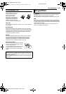
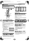
Connecting to a DV Device
A Connect the unit’s [S-VIDEO INPUT] or [VIDEO INPUT]
connector on the front panel to the camcorder’s s-video or video
output connector.
B Connect the unit’s [AUDIO INPUT] connectors on the front
panel to the camcorder’s audio output connectors.
Connecting to Another Recorder
A Connect the unit’s [S-VIDEO INPUT] or [VIDEO INPUT]
connector to another recorder’s s-video or video output
connector.
B Connect the unit’s [AUDIO INPUT] connectors to another
recorder’s audio output connectors.
Plug the end of the mains power cord into a mains outlet.
● APLEASEB and AWAITB blink alternately on the front display
panel when the AC plug of the mains power cord is
connected into a mains outlet. After a short while, A32**B
blinks on the front display panel and starts to count down.
It takes approximately 50 seconds for the unit to be turned
on. This is not a malfunction.
Basic Connections
ATTENTION:
Connect the AC plug only after all connections to the TV has
been completed.
● Make sure the package contains all of the accessories listed in
ASPECIFICATIONSB (A pg. 82).
● Place the unit on a stable, horizontal surface.
TV
Audio/Video
cable
(not supplied)
S-video cable
(not supplied)
To [S -VIDEO
INPUT]
To
[S-VIDEO
OUTPUT]
S-video cable
(not supplied)
To
[AUDIO/
VIDEO
OUTPUT]
Audio/Video
cable
(supplied)
Component video
cable
(not supplied)
To
[VIDEO
OUTPUT]
Back of unit
To
[COMPONENT
VIDEO OUT
(Y/P
B
/P
R
)]
To [AUDIO/VIDEO INPUT]
Mains power cord
Mains outlet
Audio/Video
cable
(not supplied)
S-video cable
(not supplied)
Camcorder
Another Recorder
BNC video
cable
(not supplied)
To [S-VIDEO
INPUT]
THESE STEPS MUST BE COMPLETED BEFORE ANY VIDEO
OPERATION CAN BE PERFORMED.
DVM700ER_00.book Page 16 Wednesday, September 20, 2006 10:03 AM