EM-C061 Computer User Manual
26
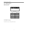
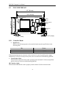
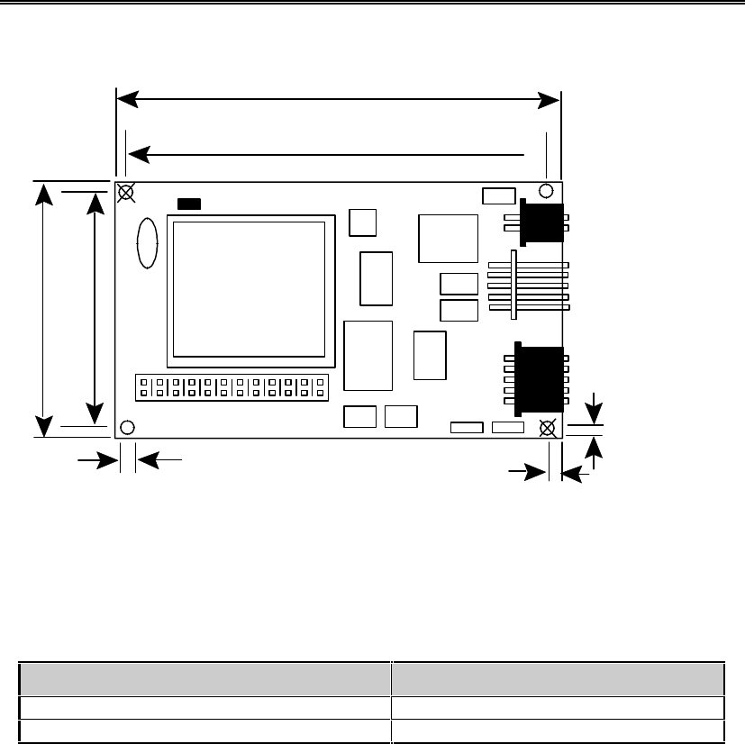
8.2 TOUCH INTERFACE
J0 •1 2 3 4 5 6 7 8 9 10 11
H1
Power
1x2 M
RS-232 Serial
2x5 M
AccuTouch
1x5 M
L
Y
S
X
H
5
P3
P2
P4
E271-2210
ELOGRAPHICS, INC.
LED
1
+
-
3.0" (76 mm)
3.3" (84 mm)
2.1" (53 mm)
1.8" (46 mm)
0.156" (4 mm)
0.15" (4 mm)
8.2.1 Controller Board
• Input Power:
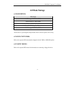
Check to see if the input power to the controller board meets the specifications in the
following table.
Pin Power
- Ground
+ +5 VDC
If the measured input power is incorrect, refer to section 9.1 to test for possible power supply
malfunctions. If you are receiving correct power, move on to the next troubleshooting guideline.
• Touch Frame Cables:
Ensure that the 5-pin touch frame cable is properly seated at header P3. If the touch problem
persists, move on to the next troubleshooting guideline.
SBC Interface Cable:
Ensure that the SBC Interface cable is properly seated at header J8 of the controller board.


