EM-C061 Computer User Manual
36
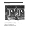
10.2.2 SIMMs Installation
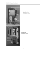
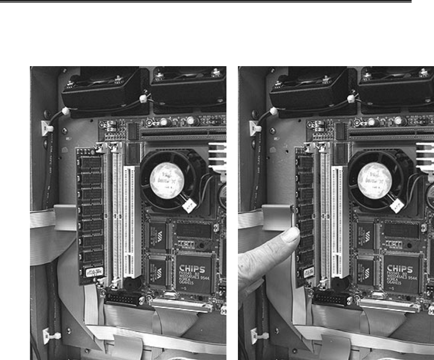
Figure A Figure B
(Photo used for illustrative purposes only. Models and configurations may vary.)
• Insert the SIMM at an angle as shown in Figure A. The SIMM will not physically fit in the
socket unless pin 1 of the SIMM matches pin 1 of the socket.
• Gently press the SIMM into the vertical position. The SIMM will snap easily into place if the
connectors are at the correct depth in the socket.
Refer to the SBC manual for memory configuration requirements.


