FX Series Programmable Controlers Applied Instructions 5
5-39
5.4.9 SFWR (FNC 38)
Operation:
The contents of the source device (S) are written to
the FIFO stack. The position of insertion into the
stack is automaticall
y
calculated b
y
the PLC.
The destination device (D) is the head address of
the FIFO stack. The contents of D identif
y
where the
next record will be stored (as an offset from D
+1
).
If the contents of D exceed the value “n-1” (n is the
len
g
th of the FIFO stack) then insertion into
the FIFO stack is stopped. The carr
y
fla
g
M8022 is
turned ON to identif
y
this situation.
Points to note:
a) FIFO is an abbreviation for ‘First-In/ First-OUT’.
b) Althou
g
h n devices are assi
g
ned for the FIFO stack, onl
y
n
-1
pieces of information ma
y
be
written to that stack. This is because the head address device (D) takes the first available
re
g
ister to store the information re
g
ardin
g
the next data insertion point into the FIFO stack.
c) Before startin
g
to use a FIFO stack ensure that the contents of the head address re
g
ister
(D) are equal to ‘0’ (zero).
d) This instruction should be used in con
j
unction with SFRD FNC 39. The n parameter
in both
instructions should be equal.
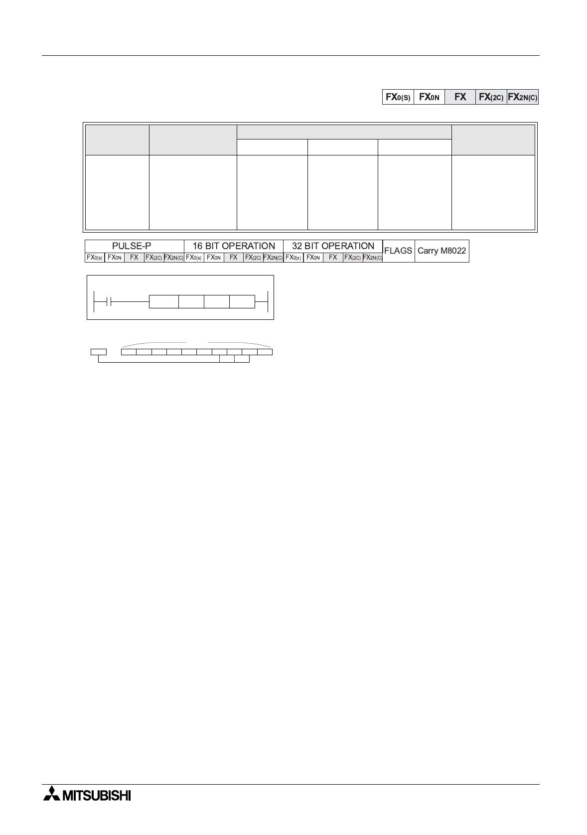
Mnemonic Function
Operands
Program steps
SDN
SFWR
FNC 38
(
Shift
re
g
ister
write)
This instruction
creates and builds
a FIFO stack n
devices lon
g
-must
be used with
SFRD FNC 39
K, H,
KnX, KnY,
KnM,KnS,
T, C, D, V, Z
KnY, KnM,
KnS,
T, C, D,
K, H,
Note:
2
≤
n
≤
512
SFWR,
SFWRP:
7 steps
X0
SFWR
D 1 K 10
[ S ] [ D ]
D 0
[ n ]
D 0 D 10 D 9 D 8 D 7 D 6 D 5 D 4 D 3 D 2 D 1
[ S ]
= 10
(3) (2) (1)
[n]


