FX Series Programmable Controllers Points Of Technique 10
10-4
10.4 Constant Scan Mode
Some times the timin
g
of operations can be a problem, especiall
y
if some co-ordination is
bein
g
attempted with a second control s
y
stem. In cases like this it is ver
y
useful to fix the
PLC’s scan time. Under normal conditions the PLC’s scan time will var
y
from one scan to the
next. This is simpl
y
because the natural PLC scan time is dependent on the number of and
t
y
pe of the active instructions. As these are continuall
y
chan
g
in
g
between pro
g
ram scans the
actual scan time is also a var
y
in
g
. Hence, b
y
usin
g
the additional pro
g
ram function identified
below, the PLC’s scan time can be fixed so that it will be the same duration on ever
y
pro
g
ram
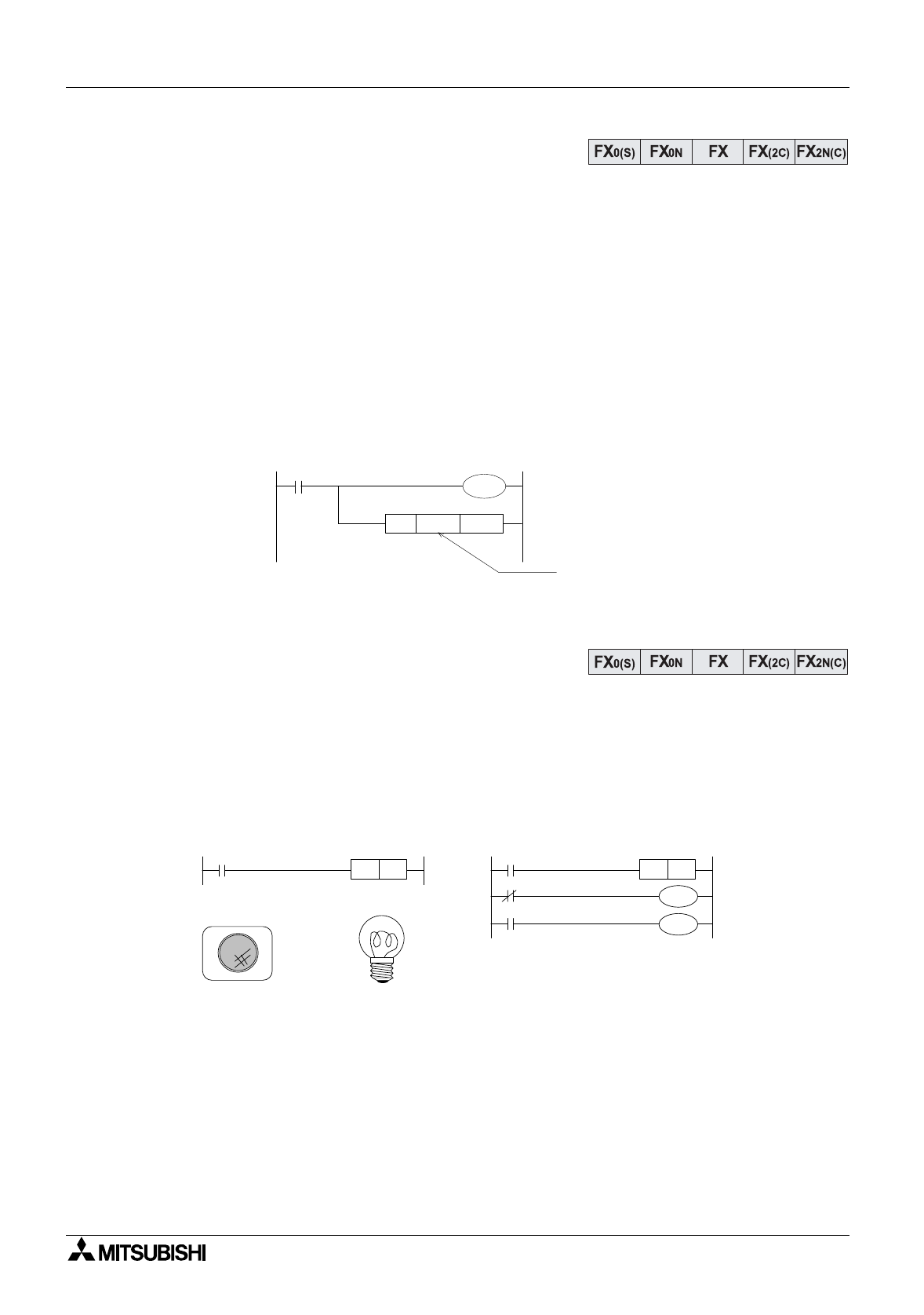
scan. The actual scan duration is set b
y
writin
g
a scan time in excess of the current lon
g
est
scan duration to special data re
g
ister D8039 (in the example the value K150 is used). If the
PLC scans the pro
g
ram quicker than the set scan time, a 'pause' will occur until the set scan
duration is reached.
This pro
g
ram example should be placed at the be
g
innin
g
of a users pro
g
ram.
10.5 Alternating ON/OFF States
It is often useful to have a sin
g
le input control or to
gg
le a situation. A basic,
y
et t
y
pical example
is the switchin
g
ON/OFF of a Li
g
ht. This can be easil
y
achieved b
y
usin
g
standard ladder
pro
g
ram to load an input and switch an output. However, this s
y
stem requires an input which is
latchable. If basic ladder steps are used to latch the pro
g
ram then it soon becomes complex
and prone to mis-pro
g
rammin
g
b
y
the user. Usin
g
the ALT instruction to to
gg
le the ON/OFF
(SET/RESET, START/STOP, SLOW/FAST) state is much simpler, quicker and more efficient.
Explanation:
Pressin
g
the momentar
y
push button X1 once will switch the lamp ON. Pressin
g
the push
button for a second time will cause the lamp to turn OFF. And if the push button is a
g
ain
pressed for a third time, the lamp is turned ON a
g
ain and so the to
gg
led status continues.
The second pro
g
ram shown identifies a possible motor interlock/control, possibl
y
a start/stop
situation.
M8000
M8039
MOV
K150
D8039
Newly set
constant scan
time = 150 msec
X 0
ALT Y 1
X 0 Y 1
X 0
Y 0
Y 1
M 0
M 0
ALT M 0
Program
example 1
Program example 2


