


11 Use of Built-in Analog
104
FX3S Series Programmable Controllers
User's Manual - Hardware Edition
11.3 Built-in analog input function
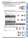
2. Averaging time
If the averaging time is set in the PLC, the averaged data will be stored as the input data.
The averaging time can be set for each channel.
Set the averaging time in the following special data registers:
Cautions regarding averaging time setting
• If the averaging time is set to "1", the immediate data is stored to the special data register.
• If the averaging time is set in the range from 2 to 4095, the average value will be calculated to conform to
the set averaging time, and the average value obtained will be stored in the special data register.
• After turning the PLC power on, the current data is stored to special data registers until the number of data
items reaches the set averaging time. After this, the average data will be stored.
• Set the averaging time in the range from 1 to 4095. If the set value is outside the setting range, an error
signal will be output.
• If the averaging time is set to "0" or smaller, the PLC will perform as if the averaging time is set to "1".
If the averaging time is set to "4096" or larger, the PLC will perform as if the averaging time is set to "4096".
For a detailed description of the error, refer to Subsection 11.3.10.
3. Error status
If an error is detected in the PLC, the error status data will be stored in the corresponding special data
register.
The following table shows the special data registers that store the error status data:
Check the ON/OFF status of each bit of the error status data register to check the description of the error.
Errors are assigned to the bits as shown in the following table. Create a program to detect errors.
For a detailed description of the error status, refer to Subsection 11.3.10.
4. Model code
When the analog built-in main unit is connected, model code "5" is stored in the corresponding special data
register.
The following table shows the special data registers that store the model code:
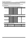
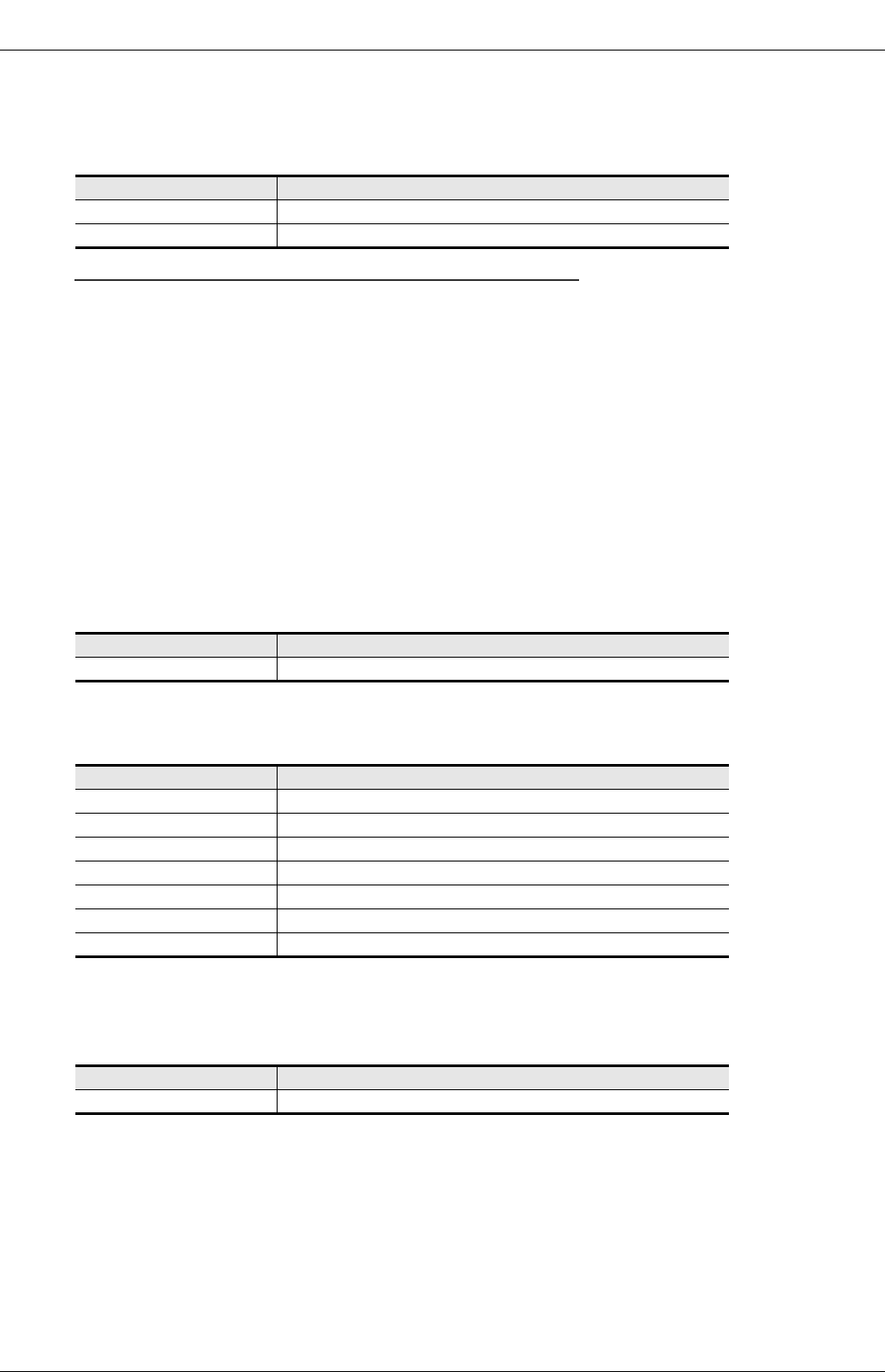
Special data register Description
D8274 Averaging time for channel-1
D8275 Averaging time for channel-2
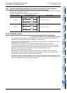
Special data register Description
D8278 Error status
Bit Description
b0 Channel-1 over-scale detection
b1 Channel-2 over-scale detection
b2 Unused
b3 Unused
b4 EEPROM error
b5 Averaging time setting error (common ch1 and ch2)
b6 to b15 Unused
Special data register Description
D8279 Model code