


EN-36
TV60, 480i(525i) – 15.73 59.94 854 x 480
TV50, 576i(625i) – 15.63 50.00 854 x 480
1080i 60 (1125i 60) – 33.75 60.00 854 x 480 *2
1080i 50 (1125i 50) – 28.13 50.00 854 x 480
480p (525p) – 31.47 59.94 854 x 480 *2
576p (625p) – 31.25 50.00 854 x 480 *2
720p 60 (750p 60) – 45.00 60.00 854 x 480 *2
720p 50 (750p 50) – 37.50 50.00 854 x 480
PC98 640 x 400 24.82 56.42 768 x 480
CGA84 640 x 400 37.86 84.13 768 x 480
CGA85 640 x 400 37.86 85.08 768 x 480
VGA60 640 x 480 31.47 59.94 640 x 480
VGA72 640 x 480 37.86 72.81 640 x 480
VGA75 640 x 480 37.50 75.00 640 x 480
VGA85 640 x 480 43.27 85.01 640 x 480
SVGA56 800 x 600 35.16 56.25 640 x 480
SVGA60 800 x 600 37.88 60.32 640 x 480 *2
SVGA72 800 x 600 48.08 72.19 640 x 480
SVGA75 800 x 600 46.88 75.00 640 x 480
SVGA85 800 x 600 53.67 85.06 640 x 480
XGA60 1024 x 768 48.36 60.00 640 x 480 *2
XGA70 1024 x 768 56.48 70.07 640 x 480
XGA75 1024 x 768 60.02 75.03 640 x 480
XGA85 1024 x 768 68.68 85.00 640 x 480
MAC13 640 x 480 35.00 66.67 640 x 480
MAC16 832 x 624 49.72 74.55 640 x 480
MAC19 1024 x 768 60.24 75.02 640 x 480
HP75 1024 x 768 62.94 74.92 640 x 480
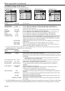
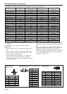
Specification of RGB signals in each computer mode of the projector
Signal mode Resolution Horizontal Vertical Normal mode
(H x V) frequency (kHz) frequency (Hz) (H x V)*1
*1 : When ASPECT in the FEATURE menu is set to
AUTO.
*2 : Available for the signal for DVI-D terminal.
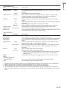
Important:
• Some computers aren’t compatible with the projec-
tor.
• The projector's maximum resolution is 854 x 480
pixels. It may not display images of higher resolu-
tions than 854 x 480 correctly.
• If the resolution and frequency of your computer
aren't shown on the table, find the compatible
resolution and frequency by changing the resolution
of your computer.
• Set COMPUTER INPUT in the SIGNAL menu to
RGB when inputting the HDTV signal as RGB sig-
nal.
• TV60 and TV50 are equivalent to 480i and 576i
respectively. When these signals are supplied to the
VIDEO or S-VIDEO signal, the signal mode is
indicated as TV60 or TV50. When they are supplied
to the COMPONENT terminal, the signal mode is
indicated as 480i or 576i.
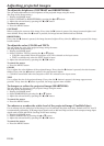
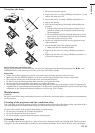
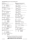
Connectors
SERIAL (8-pin)
1 R(RED)/CR
2
G(GREEN)/Y
3
B(BLUE)/CB
4 GND
5 GND
6 GND
7 GND
8 GND
9 DDC5V
10 GND
11 GND
12 DDC Data
13 HD/CS
14 VD
15 DDC Clock
1 TXD IN
2 ––
3 ––
4 GND –
5 ––
6 ––
7 RXD OUT
8 ––
1
35
2
68
15
11
6
10
15
Pin No. Name I/O
COMPUTER IN / COMPONENT VIDEO IN
(Mini D-SUB 15-pin)
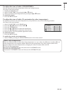
Pin No. Spec.
DVI-D (HDCP)
(DVI-D 24-pin)
PIN No.
SPEC
PIN No.
SPEC
1 DATA 2- 13 –
2 DATA 2+ 14 +5V Power
3 DATA 2 Shield 15 Ground
4 – 16 Hot Plug Detect
5 – 17 DATA 0-
6 DDC Clock 18 DATA 0+
7 DDC Data 19 DATA 0 Shield
8 –
2
0 –
9 DATA 1- 21 –
10 DATA 1+ 22 Clock Shield
11 DATA 1 Shield 23 Clock+
12 – 24 Clock-
1724
16 9
8
1
Specifications (continued)