


24 2. TV Connections
In Canada call 1(800) 450-6487 for assistance.
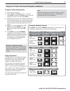
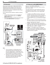
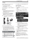
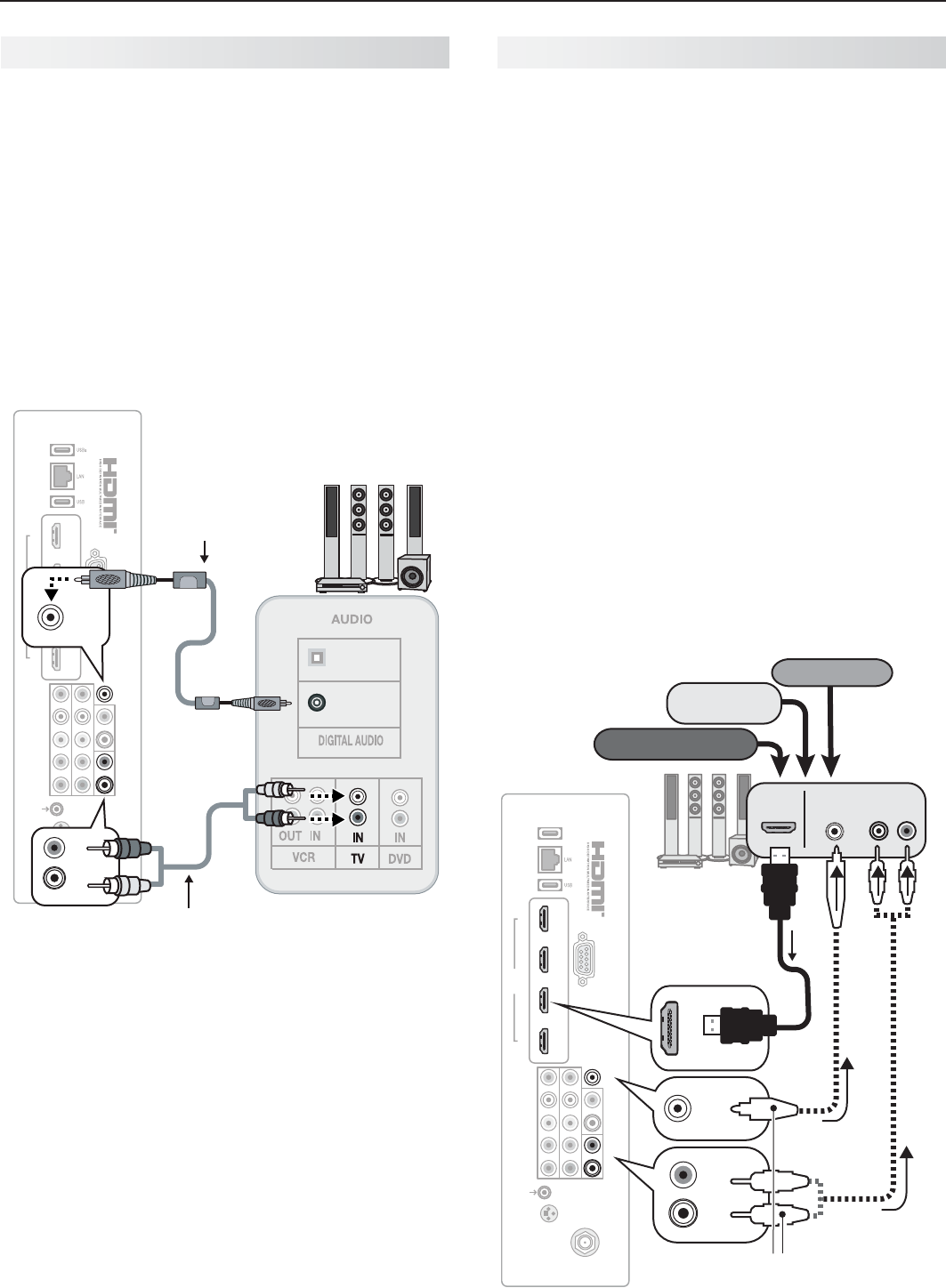
A/V Receiver
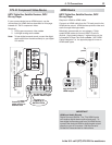
Most setups require either a digital audio cable or
analog stereo audio cables. To send audio from TV
channels received on the
ANT
input or devices con-
nected directly to the TV, you must use one of the
connections shown below. Usually, only one of these
connections is required.
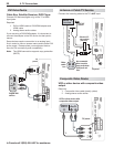
The TV makes all audio available in digital and analog
formats:
Analog audio coming into the TV is available as •
output in digital stereo format on the
DIGITAL
AUDIO OUTPUT
jack.
Digital incoming audio is available as analog output •
on the
AVR AUDIO OUTPUT L
and
R
jacks.
1 2 3 4
HDMI
AVR AUDIO OUTPUT
DIGITAL
AUDIO
OUTPUT
RS-232C
3D
GLASSES
EMITTER
ANT
INPUT 2
INPUT 1
DVI/PC
L
R
L
R
INPUT
IR-
NetCommand
Output/External
Controller Input
Pb Pr
LR
Y/ VIDEO
OPTICAL
INPUT
COAXIAL
INPUT
COAXIAL
INPUT
DIGITAL
AUDIO
OUTPUT
DIGITAL
AUDIO
OUTPUT
AVR AUDIO OUTPUT
L
R
AVR AUDIO OUTPUT
L
R
TV
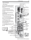
Digital coaxial
cable (for a digital
A/V receiver)
Stereo analog cables
(for an analog A/V receiver)
A/V receiver
back panel
Note:
On rare occasions, an HDMI signal may be •
copy-restricted and cannot be output from
the TV as a digital signal. To hear these copy-
protected signals through the A/V receiver, use
the connection for an analog A/V receiver.
Check the A/V receiver’s Owner’s Guide for •
information concerning use of the digital input
and switching between digital sound and
analog stereo sound from the TV.
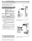
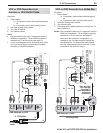
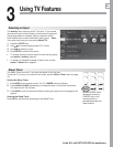
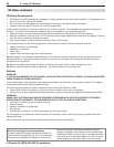
A/V Receiver with HDMI Output
Required: One HDMI-to-HDMI cable
Optional: One digital coaxial audio cable or analog
stereo audio cables
This option allows you to view content from devices
connected to an A/V receiver. The A/V receiver can
send audio and video to the TV over a single HDMI
cable.
In addition to the HDMI connection, you can use •
an audio connection from one of the TV’s audio
outputs. The optional audio connection allows you
to hear, through the A/V receiver, devices con-
nected to the TV only, e.g., an antenna on the
ANT
input.
You may be able to use the TV’s remote control (in •
TV
mode) to operate connected CEC-enabled HDMI
devices. See Appendix C, page 73.
L75-A91.• This setup allows you to use NetCom-
mand-controlled audio and video switching over the
HDMI cable. See “Case 3: Automatic Audio and
Video Switching via HDMI” on page 60.
L75-A91.• To use NetCommand to supplement
HDMI control of a CEC-enabled A/V receiver, note
the recommendations under “More About Using an
HDMI Connection,” page 60.
1 2 3 4
HDMI
AVR AUDIO OUTPUT
DIGITAL
AUDIO
OUTPUT
RS-232C
3D
GLASSES
EMITTER
ANT
INPUT 2
INPUT 1
DVI/PC
L
R
L
R
INPUT
IR-
NetCommand
Output/External
Controller Input
Pb Pr
LR
Y/ VIDEO
HDMI
OUT
A/V receiver
with HDMI
output
Any connec-
tion types
(can be HD or
SD video)
AUDIO
IN
DIGITAL
AUDIO IN
VCR
Cable box
DVD player
DIGITAL
AUDIO
OUTPUT
DIGITAL
AUDIO
OUTPUT
AVR AUDIO OUTPUT
L
R
L
R
Optional audio
connection
(analog or digital)
TV
HDMI
cable
or