


MODEL: WD-52327 / WD-62327
Page 27
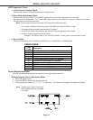
Purpose:
Measuring
Instrument
Test Point
Measuring
Range
Input Signal
Ext. Trigger
Input Terminal
Symptom:
Purpose:
Measuring
Instrument
Test Point
Measuring
Range
Input Signal
Ext. Trigger
Input Terminal
Symptom:
Oscilloscope
JA-22 & JB-3
------
------
Color Bars
Video Input
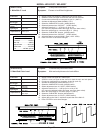
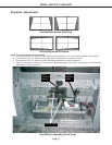
[Video Circuit]
1. Main/Sub Y Level
To set picture luminance
Excess or insufficient brightness.
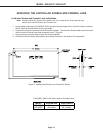
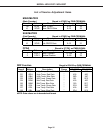
1. Supply a color bar signal to a Video Input (not an RF input).
2. Select the color bar signal for both the main and sub pictures.
3. Connect the oscilloscope to connector JA pin 22. (Main-Y)
4. Activate the Adjustment Mode (MENU-5-7-5-7)
5. Select the “MAIN MTRX” function. (AUDIO button)
6. Select adjustment Item “39 SCNT”. (VIDEO button)
7. Adjust the data for 0.71 ~ 0.76 Vp-p at JA pin 22.
(If it cannot be adjusted within this range, set to the lower value)
8. Move the oscilloscope to connector JB pin 3. (Sub-y)
9. Select the “SUB MTRX” function. (AUDIO button)
10. Select adjustment Item “39 SCNT”. (VIDEO button)
11. Adjust the data to equal the MAIN-Y Gain (+0.0V -0.05V).
12. Press “ENTER” to save data changes.
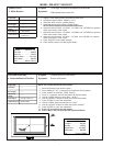
To set the sub picture color level.
Main and sub pictures color levels differs.
[Video Circuit]
2. Main/Sub Color Level
Oscilloscope
------
200mV/div
20usec/div
Color Bars
Video Input
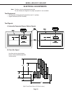
1. Supply a color bar signal to a Video Input.
2. Select the color bar signal as the source for both the main and sub picture.
3. Connect an oscilloscope to connector JA pin 20 (main Cr).
3. Activate the Adjustment mode (MENU-5-7-5-7)
4. Select the “MAIN MTRX” function (AUDIO button).
5. Select adjustment item “41 SCLR” (VIDEO button)
6. Adjust the data for 0.81 ~ 0.86 Vp-p min. at JA pin 20.
(If it cannot be adjusted within this range, set to the lower value).
7. Move the oscilloscope to connector JB pin 5 (sub Cr).
8. Select the “SUB MTRX” function (AUDIO button).
9. Select adjustment item “41 SCLR” (VIDEO button).
10. Adjust data so the Sub Cr amplitude equals that of the Main Cr.
11. Press “ENTER to save data changes.
JA-20 & JB-5
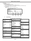
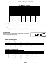
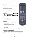
CIRCUIT ADJUST MODE
A
ctivate …….. MENU-5-7-5-7
Function …...………..AUDIO
Item No. ……….…….VIDEO
Adjust Data ….…….ADJUST
Save Data …. ………ENTER
Exit …………..MENU (twice)