


MODEL: WD-52327 / WD-62327
Page 28
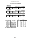
Purpose:
Measuring
Instrument
Test Point
Measuring
Range
Input Signal
Ext. Trigger
Input Terminal
Symptom:
Purpose:
Measuring
Instrument
Test Point
Measuring
Range
Input Signal
Ext. Trigger
Input Terminal
Symptom:
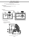
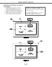
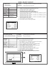
[PICTURE POSITION]
4. Horizontal/Vertical Position
To center picture on the screen.
Picture is off center.
----
----
------
-------
Internal Pattern “B”
External Input
NOTE: The TV must be on a flat level surface.
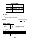
1. Select an External Input with no signal.
2. Press “MENU-5-7-5-7” in sequence (activates the Service Mode).
3. Press “AUDIO” to select the “FPGA” function.
4. Press “2” to activate internal Test Pattern B. (Shown below)
5. Use the “VIDEO” button to select Item “1 H-DLY”.
6. Use the “ADJUST” buttons to center the picture Horizontally..
7. Press “ENTER” to save the adjustment.
8. Use the “VIDEO” button to select Item “2 V-DLY”.
9. Use the “ADJUST” buttons to center the picture Vertically.
10. Press “ENTER” to save the adjustment.
11. Press “9” to terminate the test pattern.
12. Press “Menu” twice to terminate the Adjustment Mode.
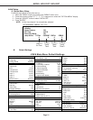
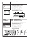
CIRCUIT ADJUST MODE
Activate …….. MENU-5-7-5-7
Function …...………..AUDIO
Item No. ……….…….VIDEO
Adjust Data ….…….ADJUST
Save Data …. ………ENTER
Exit ………….."9" then "MENU"
------
------
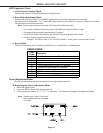
White Raster
Video Input
[Video Circuit]
3. White Balance
To set high, mid and low temperature white levels.
White areas have a color tint.
1. Supply a 100% white raster to an External Video Input.
3. Activate the Service Mode. (MENU-5-7-5-7)
4. Select the “DDP” function. (AUDIO button)
5. Select adjustment Items with the VIDEO button.
NOTE: Data is displayed in the hexadecimal format.
6. Adjust the data for Items “120 GGH”, “121 GRH and “122 GBH” for optimum
white at the center of the screen.
7. Adjust the data for Items “123 GGM”, “124 GRM and “125 GBM” for optimum
white at the center of the screen.
8. Adjust the data for Items “126 GGL”, “127 GRL and “128 GBL” for optimum
white at the center of the screen.
9. Press “ENTER” to save data changes.
10. Press “MENU” twice to exit the Service Mode.
CIRCUIT ADJUST MODE
A
ctivate …….. MENU-5-7-5-7
Function …...………..AUDIO
Item No. ……….…….VIDEO
Adjust Data ….…….ADJUST
Save Data …. ………ENTER
Exit …………..MENU (twice)