


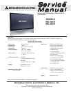


MODEL: WD-52327 / WD-62327
Page 3
INTRODUCTION ...............................................................................................................................5
PRODUCT SAFETY NOTICE ...........................................................................................................5
SAFETY PRECAUTIONS .................................................................................................................6
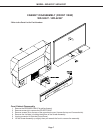
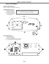
DISASSEMBLY
WD-52327 & WD-62327
Front Cabinet Components .................................................................................................... 7
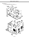
Rear Cabinet Components .....................................................................................................8
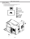
CHASSIS REMOVAL
Chassis removal procedure .................................................................................................... 9
Shield Removal .................................................................................................................... 10
Chassis PWB locations ....................................................................................................... 11
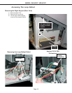
Accessing the Lamp Ballast ................................................................................................ 12
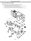
OPTICAL ENGINE REPLACEMENT
Optical Engine Mounting ...................................................................................................... 13
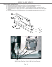
Removing the Optical Engine ............................................................................................... 14
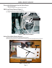
Removing DMD Heat Sensor ................................................................................................ 15
Removing Bottom Plate & Black Support Bracket. ............................................................... 15
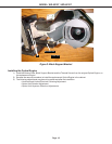
Installing the Optical Engine ................................................................................................ 16
SERVICING THE LENTICULAR SCREEN AND FRESNEL LENS
Removal of the Lenticular Screen and Fresnel Lens ............................................................. 17
Installation of the Lenticular Screen and Fresnel Lens.......................................................... 19
ELECTRICAL ADJUSTMENTS
Equipment .................................................................................................................................... 20
Initial Setup (Option Menu)............................................................................................................ 21
Main Menu Defaults ...................................................................................................................... 21
A/V Memory Defaults.................................................................................................................... 22
LED Indications ............................................................................................................................ 22
LED Dignostic Check.................................................................................................................... 23
Circuit Adjustment Mode ............................................................................................................... 23
Adjustment Items List ................................................................................................................... 25
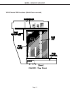
Activating Internal Test Patterns .................................................................................................... 26
Adjustment Procedures ................................................................................................................ 27
Main & Sub Y level adjustments .......................................................................................... 27
Main & Sub Color level adjustments..................................................................................... 27
White Balance Adjustments ................................................................................................. 28
Horizontal & Vertical Position adjustments .......................................................................... 28
Mechanical Adjustments ............................................................................................................... 29
Required Front Disassembly ................................................................................................ 29
Required Rear Disassembly ................................................................................................. 29
Picture Rotation Adjustment ............................................................................................... 30
Horizontal & Vertical Keystone Distortion adjustments......................................................... 31
QUICK REFERENCE PART LIST ..................................................................................................... 32
Service Parts List ........................................................................................................................... 33
Screen Parts List ............................................................................................................................ 41
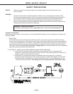
CIRCUITRY BLOCK DIAGRAMS
Standby power Supplies....................................................................................................... 42
Switched Supplies ...............................................................................................................42
CONTENTS