


17
17
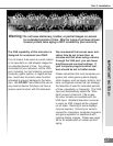
Additional connection cables are not
provided with the TV. They should be
available at most electronic stores.
Part II: Installation
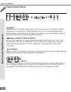
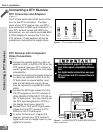
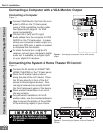
Connecting a VCR
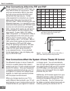
Antennas or Wall Outlet Cable
(Figure 1)
1
Connect the incoming cable to ANT-A on
the TV back panel.
Connect two coaxial cables as follows:
2
One from LOOP-OUT on the TV back panel to
ANTENNA IN on the VCR back panel.
3
One from VCR back panel ANTENNA OUT to
ANT-B on the TV back panel.
4
Now complete gur e 3, steps 1- 2.
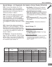
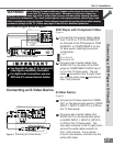
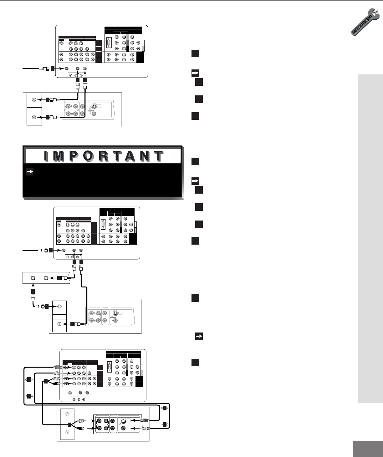
Connecting a VCR
Cable Box
(Figure 2)
1
Connect the incoming cable to ANT-A on
the TV back panel.
Connect three coaxial cables as follows:
2
One from LOOP-OUT on the TV back panel to
IN on the back of the cable box.
3
One from OUT on the back of the cable box to
ANTENNA IN on the VCR back panel.
4
One from ANTENNA OUT on the VCR back
panel to ANT-B on the TV back panel.
5
Now complete gur e 3, steps 1- 2.
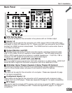
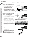
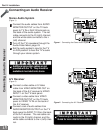
Composite Video with Audio or
S-Video with Audio
(Figure 3)
1
Connect a video cable from VIDEO
OUT on the VCR back panel to VIDEO
INPUT-1, INPUT-2 or INPUT-3 on the TV
back panel.
If you have a S-VHS VCR, follow the same
steps using the S-Video terminals on the VCR
and TV (in place of the composite terminals).
2
Connect a set of audio cables from
AUDIO OUT on the VCR back panel to
AUDIO INPUT-1, INPUT-2, or INPUT-3
on the TV back panel. The red cable
connects to the R (right) channel and
the white cable connects to the L (left)
channel. If your VCR is mono (non-ste-
reo), connect only the white (left) cable.
Y
G
Pb
B
Pr
R
V
H
HIGH RESOLUTION INPUT
INPUT
3 PIP
S-VIDEO
VGA
640X 480, 60HZ
COMPONENT 480i /480p
1 (YPrPb)
2 (YPrPb)
DTV (YPrPb/GRBHV)
480i /480p /1080i
VIDEO
MONITOR
IR EMITTER HOME THEATER
21
STB
OUTPUT
AUDIO-
LEFT/
(MONO)
AUDIO-
RIGHT
AUDIO-
LEFT/
(MONO)
AUDIO-
RIGHT
ANT-BLOOP OUTANT-A
IN
OUT
Antenna
AUDIO OUT
AUDIO IN
VIDEO OUT
(Y/C)
MONITOR
1
L
R
L
R
1
2
VCR back panel
If your VCR has a video
channel or RF ON/OFF
switch, set to OFF.
Attach
only
one
cable
type
1
1
Attach
only
one
cable
type
1
1
2
2
TV back panel
White
Red
White
Red
Figure 3. Connecting the VCR Audio/Video.
AUDIO OUT
AUDIO IN
VIDEO OUT
(Y/C)
MONITOR
1
L
R
L
R
1
2
IN
OUT
Antenna
VCR back panel
Y
G
Pb
B
Pr
R
V
H
HIGH RESOLUTION INPUT
INPUT
3 PIP
S-VIDEO
VGA
640X 480, 60HZ
COMPONENT 480i /480p
1 (YPrPb)
2 (YPrPb)
DTV (YPrPb/GRBHV)
480i /480p /1080i
VIDEO
MONITOR
IR EMITTER HOME THEATER
21
STB
OUTPUT
AUDIO-
LEFT/
(MONO)
AUDIO-
RIGHT
AUDIO-
LEFT/
(MONO)
AUDIO-
RIGHT
ANT-BLOOP OUTANT-A
TV back panel
Incoming Cable
Cable Box
Rear Terminals
INOUT
1
2 4
2
3
3
4
Figure 2. Connecting VCR with cable box.
AUDIO OUT
AUDIO IN
VIDEO OUT
(Y/C)
MONITOR
1
L
R
L
R
1
2
Y
G
Pb
B
Pr
R
V
H
HIGH RESOLUTION INPUT
INPUT
3 PIP
S-VIDEO
VGA
640X 480, 60HZ
COMPONENT 480i /480p
1 (YPrPb)
2 (YPrPb)
DTV (YPrPb/GRBHV)
480i /480p /1080i
VIDEO
MONITOR
IR EMITTER HOME THEATER
21
STB
OUTPUT
AUDIO-
LEFT/
(MONO)
AUDIO-
RIGHT
AUDIO-
LEFT/
(MONO)
AUDIO-
RIGHT
ANT-BLOOP OUTANT-A
TV back panel
Incoming Cable
IN
OUT
Antenna
VCR back panel
1
2 3
3
2
Figure 1. Connecting VCR with antennas or wall outlet
cable.