


28 Chapter 2. Connecting
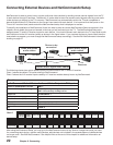
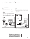
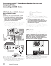
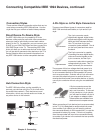
A/V Receiver (Stereo System)
Figure 7
A digital audio cable and stereo audio cables are required.
These cables are not included with the TV.
1. To connect an analog A/V receiver:
Connect a set of stereo audio cables from OUTPUT
AUDIO 2 on the TV back panel to the TV AUDIO
INPUT on the back of the A/V receiver. The red cable
connects to the R (right) channel and the white cable
connects to the L (left) channel.
2. To connect a digital A/V receiver with Dolby®
Digital surround sound:
Connect one end of the digital audio cable supplied
with the TV to DIGITAL AUDIO on the back of the
TV. Connect the other end to the COAXIAL DIGITAL
INPUT on the back of the A/V receiver.
Check the A/V receiver’s Owner’s Guide for information
concerning use of the digital input and switching between
digital sound and analog stereo sound from the TV.
*/ */ */ */ */ */ */ */065 065 065 065
"69 $% 5"1& 5"1& 7$3 7$3 57 %7%
.0/*5037$37$357%7%
.0/*5037$37$357%7%
065
065
*/
*/
*/
*/
*/
*/
*/
*/
065 065
065 065
$&/5&3
46#
800'&3
'30/5463
3&$
4063$&
-*/&065
13&065
463306/%
41&",&347.*/
'30/5
41&",&34"7.*/
'30/5
41&",&34#7.*/
$&/5&3
7.*/
-
-
-
-
3
-
3
3
3
5)*4%&7*$&$0.1-*&48*5)1"350'5)&
'$$36-&401&3"5*0/*446#+&$5505)&
'0--08*/(580$0/%*5*0/45)*4%&7*$&
.":/05$"64&)"3.'6-*/5&3'&3&/$&"/%
5)*4%&7*$&.645"$$&15"/:*/5&3'&3&/$&
3&$&*7&%*/$-6%*/(*/5&3'&3&/$&5)"5.":
$"64&6/%&4*3&%01&3"5*0/
."/6'"$563&%6/%&3-*$&/4&'30.%0-#:-"#03"503*&4-*$&/4*/(
$03103"5*0/%0-#:130-0(*$"/%5)&%06#-&%4:.#0-"3&
53"%&."3,40'%0-#:-"#03"503*&4$03103"5*0/
$01:3*()5%0-#:-"#03"503*&4*/$"--3*()54
3&4&37&%
*/165
015*$"-
*/165
$0"9*"-
*/165
$0"9*"-
%*(*5"-"6%*0
48*5$)&%
6/48*5$)&%
"$7)[
505"-8"."9
"$065-&54
.*546#*4)*
"6%*07*%&03&$&*7&3
.0%&-.73
108&34611-:
108&3$0/46.15*0/
7)[
87"
%*453*#65&%#:
.*546#*4)*$0/46.&3&-&$530/*$4".&3*$"
*/$
"5-"/5*$#-7%."%&*/
+"1"/
/03$3044("'"#3*26&&/
+"1"/
"7*4
3*426&%&$)0$&-&$530/26&
/&1"4&/-&7&3
3*4,0'&-&$53*$4)0$,
%0/0501&/
"/5&//"
7
7
'.
".
(/%
"560
45"/%#:
0/
0''
S
T
47*%&0
7*%&0
"6%*0
8"3/*/(
*/
57
-
3
*/165
$0"9*"-
COMPONENT
YPbPr (480i/480p/720p/1080i)
INPUT
1
2
S-VIDEO
VIDEO
AUDIO-
LEFT/
(MONO)
AUDIO-
RIGHT
DTV/CABLE/
VHF/UHF
ANT 1 / MAIN
ANT 2 / AUX
DIGITAL
AUDIO
OUTPUT
CableCARD™ USE WITH ANT 1 CARD TOP
1
2
Y
Pb
Pr
AUDIO-
LEFT/
(MONO)
AUDIO-
RIGHT
OUTPUT
AUDIO
OUTPUT
RECORD
OUTPUT
DVI
Analog Audio
1 2
VIDEO
AUDIO-
LEFT/
(MONO)
AUDIO-
RIGHT
MONITORLINK™/HDMI
VIDEO 480i/480p/720p/1080i
AUDIO PCM LINEAR
1
2
IEEE 1394
INPUT/
OUTPUT
Net Command
IR EMITTER
¸
',INK
¸
INPUT
PC - 60Hz
VGA, W-VGA,
SVGA, W-SVGA,
XGA, 1280 X 720
6TFPOMZJG
DPOOFDUJOHB
%PMCZEJHJUBM
"7SFDFJWFS
"73FDFJWFS3FBS1BOFM
57#BDL1BOFM
4FDUJPO
Figure 7. Connecting an A/V receiver
Note: On rare occasions, an HDMI signal may be copy-
restricted and cannot be output from the TV as a digital
signal. To hear these copy-protected signals through the
A/V receiver, use connections for analog A/V receivers.
MP3 audio from memory cards cannot be connected
to digital audio. To listen to MP3 playback from the TV
MediaCommand memory card player through your A/V
receiver, use the connections for an analog A/V receiver.
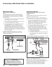
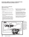
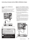
Satellite Receiver or Other Device with
S-Video
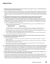
Figure 8
An S-Video cable and audio cables are required. These are not
included with the TV.
1. Connect an S-Video cable from VIDEO OUT on the
satellite receiver back panel to INPUT-2 S-VIDEO on
the TV back panel.
2. Connect a set of audio cables from AUDIO OUT on
the satellite receiver back panel to INPUT-2 AUDIO
on the TV back panel. The red cable connects to
the R (right) channel and the white cable connects to
the L (left) channel.
Note: Refer to the Satellite Receiver Owner’s
Guide for Dish Antenna connections
COMPONENT
YPbPr (480i/480p/720p/1080i)
INPUT
1
2
S-VIDEO
VIDEO
AUDIO-
LEFT/
(MONO)
AUDIO-
RIGHT
DTV/CABLE/
VHF/UHF
ANT 1 / MAIN
ANT 2 / AUX
DIGITAL
AUDIO
OUTPUT
CableCARD™ USE WITH ANT 1 CARD TOP
1
2
Y
Pb
Pr
AUDIO-
LEFT/
(MONO)
AUDIO-
RIGHT
OUTPUT
AUDIO
OUTPUT
RECORD
OUTPUT
DVI
Analog Audio
1
2
VIDEO
AUDIO-
LEFT/
(MONO)
AUDIO-
RIGHT
MONITORLINK™/HDMI
VIDEO 480i/480p/720p/1080i
AUDIO PCM LINEAR
1
2
IEEE 1394
INPUT/
OUTPUT
Net Command
IR EMITTER
¸
',INK
¸
INPUT
PC - 60Hz
VGA, W-VGA,
SVGA, W-SVGA,
XGA, 1280 X 720
:$
-
3
-
3
7*%&0065
"6%*0065
"6%*0*/
57CBDLQBOFMTFDUJPO
"OZ47JEFP%FWJDF
8IJUF
3FE
8IJUF
3FE
Note: NetCommand® will assume you connected
your Satellite Receiver to Input-2. If you add a second
Satellite Receiver or use any other inputs for your
Satellite Receiver, this change must match in the
NetCommand system. See Editing NetCommand
Setup in Chapter 3 for more information.
Figure 8. Connecting a Satellite Receiver with S-Video
Connecting an A/V Receiver (Stereo System)
Connecting a Satellite Receiver or Other Device with S -Video