


4 - 3 4 - 3
MELSEC-Q
4 SETUP AND PROCEDURES BEFORE OPERATION
4.3 Part Identification Nomenclature
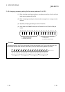
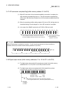
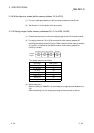
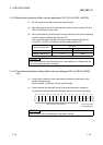
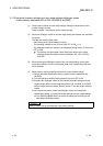
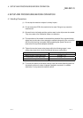
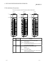
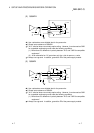
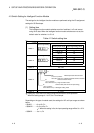
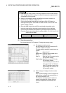
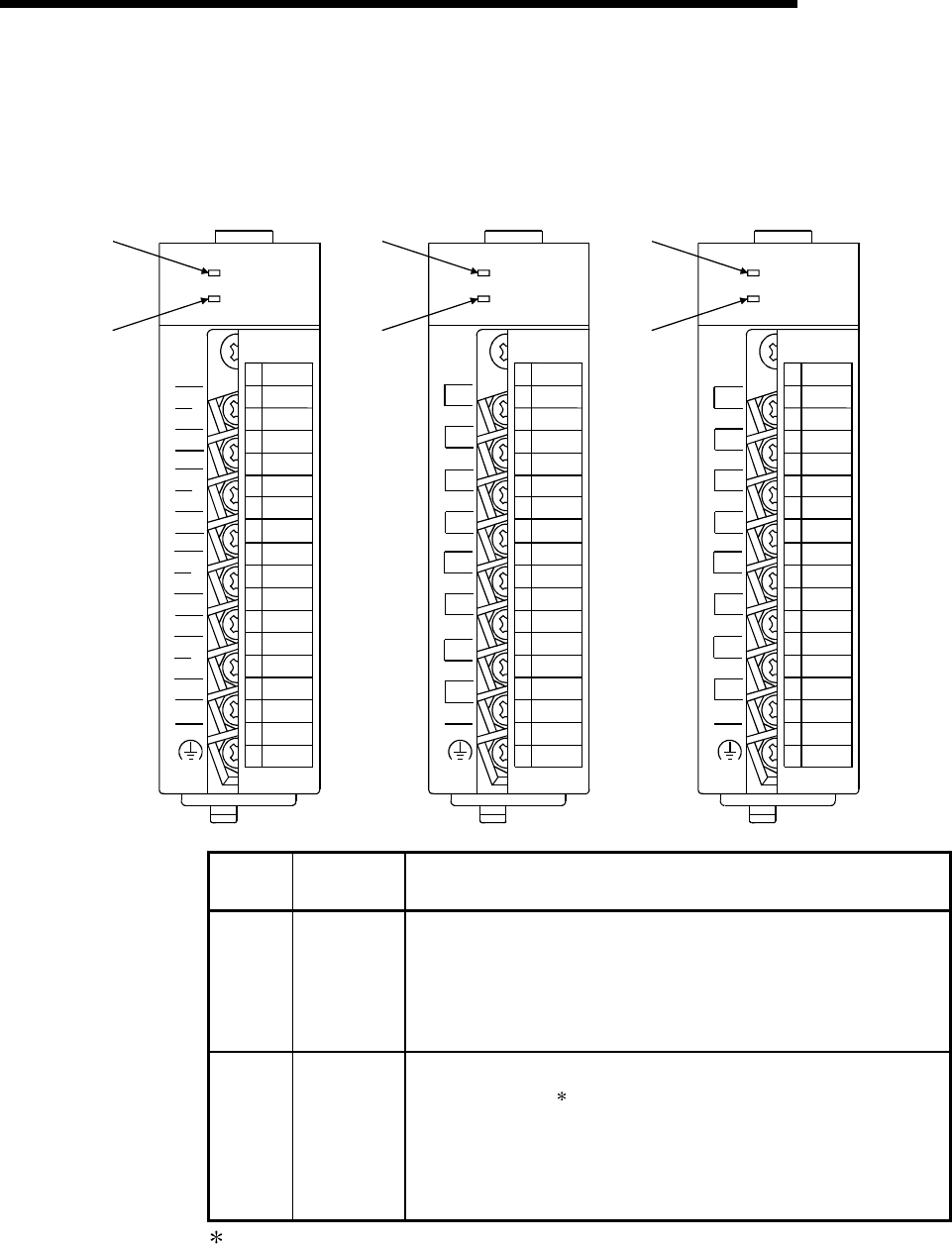
The name of each part of the A/D converter module is listed below.
1)
2)
Q64AD
Q64AD
RUN
ERROR
I+
V-
V+
SLD
(FG)
A/D
0-±10V
0-20mA
C
H
1
C
H
2
I+
V-
V+
SLD
I+
V-
V+
SLD
C
H
3
C
H
4
I+
V-
V+
SLD
A.G.
1)
2)
Q68ADV
Q68ADV
RUN
ERROR
C
H
4
C
H
3
V-
V+
V-
V+
(FG)
A/D
0-±10V
C
H
8
C
H
7
V-
V+
V-
V+
C
H
6
C
H
5
V-
V+
V-
V+
A.G.
C
H
2
C
H
1
V-
V+
V-
V+
1)
2)
Q68ADI
Q68ADI
RUN
ERROR
C
H
4
C
H
3
I-
I+
I-
I+
(FG)
A/D
0-20mA
C
H
8
C
H
7
I-
I+
I-
I+
C
H
6
C
H
5
I-
I+
I-
I+
A.G.
C
H
2
C
H
1
I-
I+
I-
I+
1
2
3
4
5
6
7
8
9
10
11
12
13
14
15
16
17
18
1
2
3
4
5
6
7
8
9
10
11
12
13
14
15
16
17
18
1
2
3
4
5
6
7
8
9
10
11
12
13
14
15
16
17
18
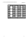
Number
Name and
appearance
Description
1) RUN LED Displays the operating status of the A/D converter module.
On : Normal operation
Flashing : During offset/gain setting mode
Off : 5V power switched off, watchdog timer error occurred, or
online module change enabled
2) ERROR LED Displays the error status of the A/D converter module.
On : Error
Off : Normal operation
Flashing : Error in switch settings
Switch No. 5 of the intelligent function module has been
set to a value other than zero "0".
Check the error code for details.