


A - 6 A - 6
INTRODUCTION
Thank you for purchasing the MELSEC-Q series PLC.
Before using the equipment, please read this manual carefully to develop full familiarity with the functions
and performance of the Q series PLC you have purchased, so as to ensure correct use.
Please forward a copy of this manual to the end user.
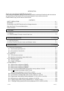
CONTENTS
SAFETY PRECAUTIONS..............................................................................................................................A- 1
REVISIONS....................................................................................................................................................A- 4
Conformation to the EMC Directive and Low Voltage Instruction ................................................................A- 9
About the Generic Terms and Abbreviations ................................................................................................A- 9
Product Structure ...........................................................................................................................................A-10
1 OVERVIEW 1- 1 to 1- 2
1.1 Features ..................................................................................................................................................1- 1
1.2 Functions Added to Function Version B and Later................................................................................ 1- 2
2 SYSTEM CONFIGURATION 2- 1 to 2- 4
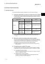
2.1 Applicable Systems................................................................................................................................. 2- 1
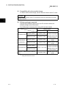
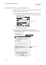
2.2 How to Check the Function Version and Software Version................................................................... 2- 3
3 SPECIFICATIONS 3- 1 to 3-26
3.1 Performance Specifications.................................................................................................................... 3- 1
3.1.1 Performance specifications list ........................................................................................................3- 1
3.1.2 I/O conversion characteristic............................................................................................................3- 2
3.1.3 Accuracy...........................................................................................................................................3- 9
3.2 Function List ............................................................................................................................................3-10
3.2.1 A/D conversion methods..................................................................................................................3-10
3.2.2 Maximum and minimum values hold function.................................................................................3-12
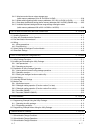
3.3 I/O Signals for the PLC CPU ..................................................................................................................3-12
3.3.1 List of I/O signals..............................................................................................................................3-12
3.3.2 Details of I/O signals ........................................................................................................................ 3-13
3.4 Buffer Memory.........................................................................................................................................3-17
3.4.1 Buffer memory assignment (Q64AD) .............................................................................................. 3-17
3.4.2 Buffer memory assignment (Q68ADV)............................................................................................3-18
3.4.3 Buffer memory assignment (Q68ADI) .............................................................................................3-19
3.4.4 A/D conversion enable/disable setting (buffer memory address 0: Un\G0)................................... 3-20
3.4.5 CH
average time/average number of times
(buffer memory addresses 1 to 8: Un\G1 to Un\G8)....................................................................... 3-20
3.4.6 Averaging processing setting (buffer memory address 9: Un\G9) .................................................3-21
3.4.7 A/D conversion completed flag (buffer memory address 10: Un\G10) .......................................... 3-22
3.4.8 Digital output values (buffer memory addresses 11 to 18: Un\G11 to Un\G18) ............................3-22
3.4.9 Write data error codes (buffer memory address 19: Un\G19)........................................................3-23
3.4.10 Setting ranges (buffer memory addresses 20, 21: Un\G20, Un\G21).......................................... 3-23
3.4.11 Offset/gain setting mode (buffer memory addresses 22, 23: Un\G22, Un\G23) .........................3-24