


4 - 11 4 - 11
MELSEC-Q
4 SETUP AND PROCEDURES BEFORE OPERATION
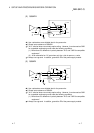
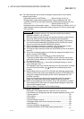
1 The mode switching (normal mode to offset/gain setting mode to normal mode)
method is given below.
• Dedicated instruction (G.OFFGAN) ............. Refer to Section 4.6 (2), (a)
• Setting made to mode switching setting (buffer memory addresses 158, 159:
Un\G158, Un\G159) and turning the operation condition setting request (Y9) from
OFF to ON ..................................................... Refer to Section 4.6 (2), (b)
• Intelligent function module switch setting ..... Refer to Section 4.5, Section 4.6 (2), (c)
(After intelligent function module switch setting, reset the PLC CPU or switch power
OFF, then ON.)
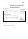
POINT
(1) Perform the offset/gain settings in the range that satisfies the conditions
specified in Section 3.1.2, (1) and (2).
When the setting exceeds this range, the maximum resolution or total accuracy
may not be within the range indicated in the performance specification.
(2) Perform the offset/gain settings separately for each channel. If channels are
set in buffer memory addresses 22 (Un\G22) and 23 (Un\G23) at the same
time, an error will occur and the ERROR LED will be lit.
(3) After the offset/gain settings are completed, verify that the offset and gain
values have been set correctly under actual usage conditions.
(4) The offset and gain values are stored into the E
2
PROM and are not erased at
power-off.
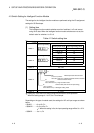
(5) At the time of offset/gain setting, turn ON the user range write request (YA) to
write the values to the E
2
PROM.
Data can be written to the E
2
PROM up to 100 thousand times.
To prevent accidental write to the E
2
PROM, an error will occur and the error
code (buffer memory address 19: Un\G19) will be stored if write is performed
26 consecutive times.
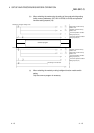
(6) If an error (error code: 40
1
) occurs during offset/gain setting, re-set the
correct offset/gain value.
The offset/gain value of the channel where the error has occurred is not written
to the A/D converter module. (
1: indicates the corresponding channel
number.)
(7) Module Ready (X0) turns from OFF to ON when the offset/gain setting mode
switches to the normal mode by the dedicated instruction (G.OFFGAN) or the
setting of the mode switching setting (buffer memory addresses 158, 159:
Un\G158, Un\G159).
Note that initial setting processing will be executed if there is a sequence
program that makes initial setting when Module Ready (X0) turns ON.
(8) Buffer memory addresses 200 (Un\G200), 202 to 233 (Un\G202 to Un\G233)
are the areas used to restore the user range settings offset/gain values when
online module change is made.
Refer to chapter 7 for details of online module change.
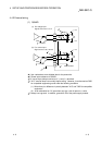
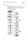
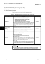
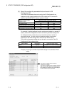
(2) Program examples
The program in the dotted area of (a) is common to (a), (b) and (c).
In this example, the I/O signals for the A/D converter module are X/Y0 to X/YF.
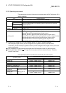
• Channel selection
...............................................................................
M0
• Offset setting
......................................................................................
M1
• Gain setting
........................................................................................
M2
• Channel change command
................................................................
M3
• Offset/gain setting value write command to the module
....................
M4
• Mode switching
....................................................................................
M5
• Channel designation storage device
...................................................
D0
• Dedicated instruction (G.OFFGAN) setting storage device
..............
D1