


Page 12
MODELS: WD-60C9 / WD-65C9 / WD-73C9 / WD-60737 / WD-65737 / WD-73737 / WD-82737
WD-65837 / WD-73837 / WD-82837
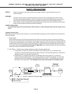
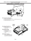
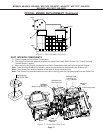
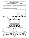
Figure 2: Duct Assembly (Top View)
DUCT INTERIOR COMPONENTS
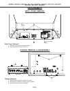
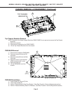
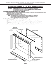
1) Figure 3 shows the Duct Interior Components.
2) The Upper Duct must be removed to replace the Lamp Door Switch PWB, Sirocco Fan, Exhaust Fan and
Thermal Sensor (1 screw).
3) When replacing the Engine, transfer the Duct Interior Components from old Engine to the new Engine.
Note: There are three Exhaust Fan Holders, one on the top and two on the bottom of the Exhaust Fan.
Note: The Exhaust Fan must be installed so the Label is facing inside the Duct.
Note: The Sirocco Fan must be installed so the Label is facing upwith the Flanges aligned onto the Guide Pins.
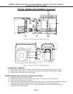
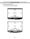
Figure 3: Lower Duct (Top View)
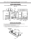
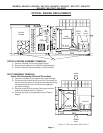
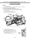
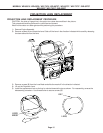
OPTICAL ENGINE REPLACEMENT (Continued)
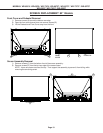
B
Latches
Latch
Latch
SIROCCO FAN
(Label Facing Up)
THERMAL
SENSOR
EXHAUST
FAN
(Behind Lamp Housing)
EXHAUST FAN
HOLDERS (3)
(1 Top - 2 Bottom)
LAMP DOOR
SWITCH
PWB
(Label Facing Inside)
FLANGES Align
Onto GUIDE PINS