17
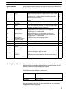
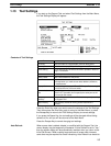
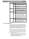
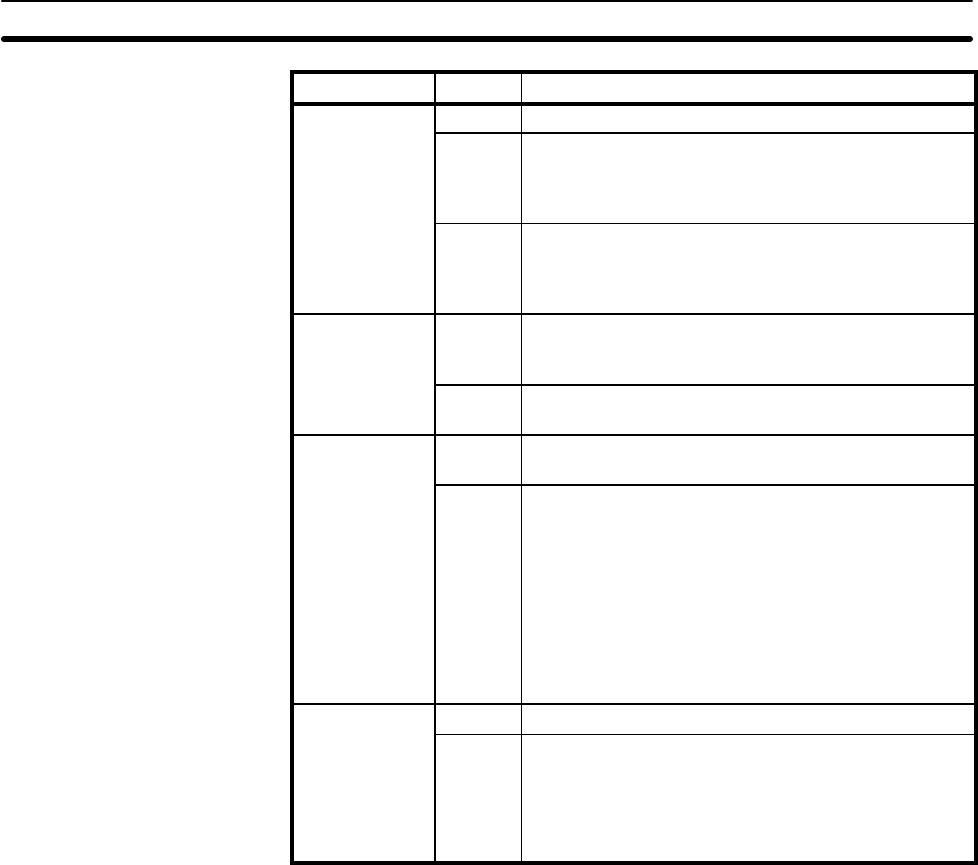
Item Settings Setting
Display grid
No Display grid is not displayed.
yg
8-dot
16-dot
32-dot
Display grid is displayed at the specified width. Screen
objects can be snapped to the grid if one of these
settings is made and the snap ON function is turned
ON (see below).
Touch
switch
Display grid is displayed at the minimum width for
touch switches. This setting is useful to draw lamps to
the same size as touch switches. It functions the same
way as the other grids.
Snap ON
function
Off Allows graphics to be drawn and screen objects to be
positioned without interference from the grid, i.e., the
grid, if displayed, is used only as a visual guide.
On Allows graphics to be drawn and screen object to be
positioned only to the intersection points of the grid.
Lamp/touch
switch number
di l
No Lamp/touch switch numbers or bit addresses are not
displayed.
display
1/16
1/4
Indicates lamp/touch switch specifications and the
allocated lamp/touch switch number or the allocated
PC bit on the display at the specified character size.
For example, “LH001015” would be displayed for a
lamp display allocated to HR 1015 using direction
connection, “TA001012”would be displayed for a touch
switch display allocated to AR 1012 using direction
connection, L000 would be displayed for lamp #0 when
not using direction connection, and T010 would be
displayed for touch switch #10.
Memory table
tb
No Memory table entry numbers are not displayed.
y
entry number
display
1/16
1/4
Indicates the allocated memory table number on the
display at the specified character size for numeral
displays, character string displays, bar graphs, and
numeral editing areas. “N” is also displayed for
numeral table entry numbers and “S” is displayed for
character string table entry numbers.
1-15 Direct Connection
The PT can be set for direct connection to an OMRON PC to allow numeral
displays, character displays, numeral editing, lamps, touch switches, and bar
graphs to be directly connected to specific bits and words in PC memory. Bits
can also be set that will change the displayed screen. This is possible only
when the NT600M-DT121/DT211 or NT20M-DT121-V1/DT131 PTs and only
when a NT600M-LK201 SYSMAC WAY Host Interface Unit is used. Also,
either an NT600M-SMR31 or NT20M-SMR31 System ROM must be used in
the PT.
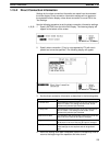
The direct connection setting in the Tool Settings greatly affects the operation
of the screen functions that read or write PC memory. Although using direc-
tion connection will greatly reduce programming burden for the PC, careful
preparation is required to coordinate PC memory and programming with the
PT settings for direct connection. The general procedure for this is as follows:
1, 2, 3...
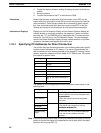
1. Design the required PT screens.
2. Allocate PC memory to the function elements of the screens, i.e., those
elements that will directly read or write PC memory. Be sure to list spe-
cific PC memory addresses, including areas, and to consider numeral
table and character string table capacities.
3. Turn ON direct connection operation in the Tool Settings.
Direct Connection Section 1-15


