


13
RQT8023
Getting started
≥You need to subscribe to a cable TV service to enjoy viewing their programming.
≥Consult your service provider regarding appropriate cable TV box.
≥If you receive your programming solely from a satellite service, the program guide in this unit will not receive program listings or
channel information. Without this information, program-based recordings cannot be made. However, recordings can still be set
manually.
The connection will allow the video cassette recorder to be used
for playback when this unit is turned off. For optimum operation, it
is recommended that this unit be connected as shown below.
≥Connection for transferring (dubbing) from video tape (➡ 14)
∫ To enjoy even higher fidelity
You can enjoy even higher fidelity, if your television has an
S-VIDEO IN or COMPONENT VIDEO IN terminals. (➡ 14)
A to W are indexes for Spanish Quick Reference.
∫ Should I use the AUDIO/VIDEO OUT terminal or
the RF OUT terminal?
If your cable TV box has both AUDIO/VIDEO OUT terminals and
RF OUT terminals, we recommend connecting the AUDIO/VIDEO
OUT terminal with the unit’s IN3 terminal. Using this connection
provides the better picture quality.
≥The S-VIDEO terminal achieves a more vivid picture than the
VIDEO terminal.
∫ Why should I connect the IR Blaster?
To download program listings, the TV Guide On Screen
TM
system
needs to be able to change channels on your cable box when the
unit is not in use. Please connect the supplied IR Blaster cable to
the G-LINK jack of the unit. After you connect the IR Blaster cable
you will be able to control your cable box using the unit’s remote
control.
Place the IR Blaster in front of the signal sensor of the cable TV box.
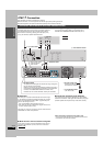
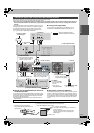
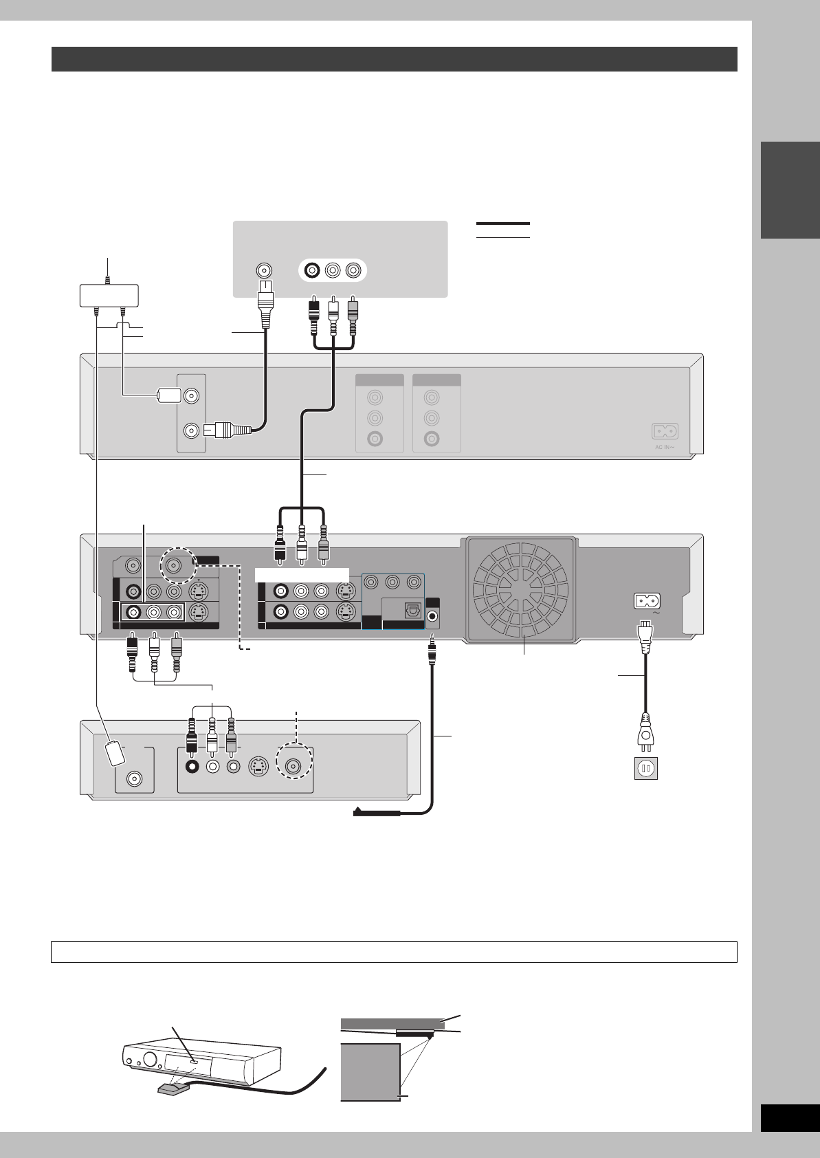
Connection with a cable TV box and video cassette recorder
S
VIDEO
VIDEO
OUT2
OUT2
OUT1
OUT1
Y
P
B
PR
COMPONENT
COMPONENT
VIDEO
VIDEO
OUT
OUT
(
48
48
0p/
p/
48
48
0i
0i
)
AC IN
S
VIDEO
VIDEO
IN3
IN3
IN1
IN1
VH
VH
F/ UHF
UHF
G
-
LINK
LINK
RF
RF
IN
IN
RF
RF
OUT
OUT
VIDEO
VIDEO
VIDEO
VIDEO
R-AUDIO-L
R-AUDIO-L
R-AUDIO-L
R-AUDIO-L
DIGITAL AUDIO OUT
DIGITAL AUDIO OUT
(PCM/BITSTREAM)
(PCM/BITSTREAM)
OPTICAL
OPTICAL
VHF/UHF
RF IN
VHF/UHF
RF OUT
AUDIO
R
AUDIO
L
VIDEO
OUT
OUT
AUDIO
R
AUDIO
L
VIDEO
IN
IN
VHF/UHF
RF IN
AUDIO IN
R L
VIDEO IN
VIDEO
RF
S-VIDEO
R L
AUDIO
OUT
IN
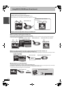
I This unit
S Cable TV box
H Audio/Video cable
P These connections to IN3 are
required for the TV Guide On
Screen
TM
system to work.
B Television
H Audio/Video cable
Q Instead of using the Audio/video
cable, you can also connect the
RF IN terminal on this unit to the
cable TV box RF OUT terminal
using the 75 ≠ coaxial cable.
R Setting the IR Blaster ➡ below
O IR Blaster
Insert the IR Blaster
jack into the G-LINK
terminal.
≥Only use the
included IR Blaster.
C
Red White Yellow
F Video cassette recorder
C
Red White Yellow
E Splitter
G 75 ≠ coaxial
cable
M AC power supply cord
Connect only after all other
connections are complete.
N To household AC outlet
(AC 120 V, 60 Hz)
J To OUT1 or OUT2
C
Red White Yellow
L Cooling fan
indicates included accessories.
indicates accessories not included.
A
D Cable from wall or
antenna signal
K To IN3
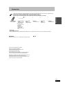
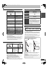
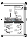
Setting the IR Blaster
T Read the cable TV box operating
instructions regarding positioning of the
signal sensor.
U If necessary, use the double sided adhesive tape (included) to
secure the IR Blaster to a flat surface.
W If you peel off the adhesive tape, the surface may
become damaged.
Once you have confirmed the cable TV box is
operating correctly, secure it by attaching the
adhesive tape.
V e.g. Television stand surface
S Cable TV box
EH50English.book Page 13 Tuesday, February 1, 2005 6:36 PM