


90 C2900M-B (1/03)
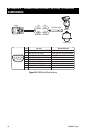
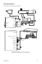
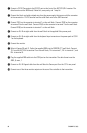
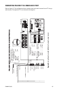
ᕡ Connect a PV130 Converter to the RS-232 port on the front of the NET101R/R-A receiver. The
data format must be 4800 baud, 8 data bits, even parity, and 1 stop bit.
ᕢ Connect the black and white striped wire from the power supply that comes with the converter
to the converter’s +12 VDC terminal and the solid black wire to the GND terminal.
ᕣ Connect TD(A) on the converter to terminal 7 on the wall block. Connect TD(B) on the converter
to terminal 8 on the wall block. Connect RD(A) on the converter to terminal 2 on the wall block.
Connect RD(B) on the converter to terminal 1 on the wall block.
ᕤ Connect an RJ-45 straight cable from the wall block to the supplied Pelco power pack.
ᕥ Connect an RJ-45 straight cable from the keyboard input connector on the power pack to COM
1 on the keyboard.
ᕦ Connect the monitor.
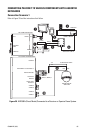
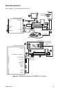
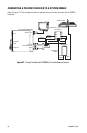
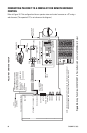
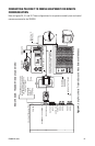
ᕧ Refer to Figures 38 and 41. Splice the supplied DB9 into the CM9760-CC1 wall block. Connect
TX- from the NET104A to terminal 2 on the wall block, TX+ to terminal 1, RX- to terminal 7, and
RX+ to terminal 8.
ᕨ Plug the supplied DB9 cable into the COM port on the transmitter. The data format must be
4800, 8, even, 1.
ᕩ Connect an RJ-45 flipped cable from the wall block to Sercom port 5 on the CC1’s rear panel.
ᕫᕾ Connect one of the three monitor outputs on the rear of the controller to the transmitter.