


C1696M-B (11/08) 21
Operating the DVR5100
The USB keyboard and mouse, and the DVR5100 control pad, provide access to most DVR5100 features and functionality.
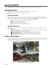
MONITORING LIVE VIDEO
The DVR5100 starts in live video mode. The following information describes how to work in this mode.
NOTE: Video panes display the cameras and layouts selected from the last logon.
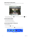
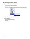
SELECTING A VIDEO PANE
When you start the unit and display a layout with several video panes, the upper-left video pane is selected by default. To select a different video
pane, click in another video pane with the mouse, or use the keyboard arrow keys [or the Joystick ] to move left, right, up, and down. The
border of the currently selected video pane changes color to reflect the current operating state of the DVR5100.
• Green: Indicates the camera is in live view mode (currently selected video screen).
• Yellow: Indicates the camera is in playback mode.
• Blue: Indicates that PTZ mode is enabled in the video pane.
• Red: Indicates that manual recording is in progress in the video pane.
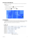
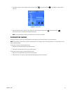
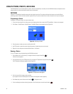
CHANGING SCREEN LAYOUT
The screen layout can be changed by pressing the F5–F8 keys. [Or, each time the Change Layout function button is pressed, one of four screen
layouts is displayed].
• Full-screen view (1 x 1): Press F5 [or “Change layout”] to display a single video pane. You can also double-click the left mouse
button in the live view mode pane for a full-screen configuration.
• Four-camera view (2 x 2): Press F6 [or “Change layout”] to display 4 video panes in rows of two.
• Nine-camera view (3 x 3): Press F7 [or “Change layout”] to display 9 video panes in rows of three.
• Sixteen-camera view (4 x 4): Press F8 [or “Change layout”] to display 16 video panes in rows of four.
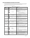
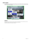
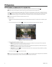
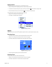
VIEWING A SPECIFIC CAMERA
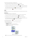
When you select a camera, its video stream is sent to the currently selected video pane. For example, if your display is set to a 2 x 2 layout and
the upper-left video pane is selected, you can choose any camera to display in that video pane (refer to Figure 14). Follow the instructions below
to move through the camera sequence, call up cameras by number, and disconnect cameras.
Figure 14. Displaying Video in a 2 x 2 Configuration