


C2673M-D (8/10) 21
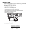
CONNECTING ALARMS
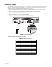
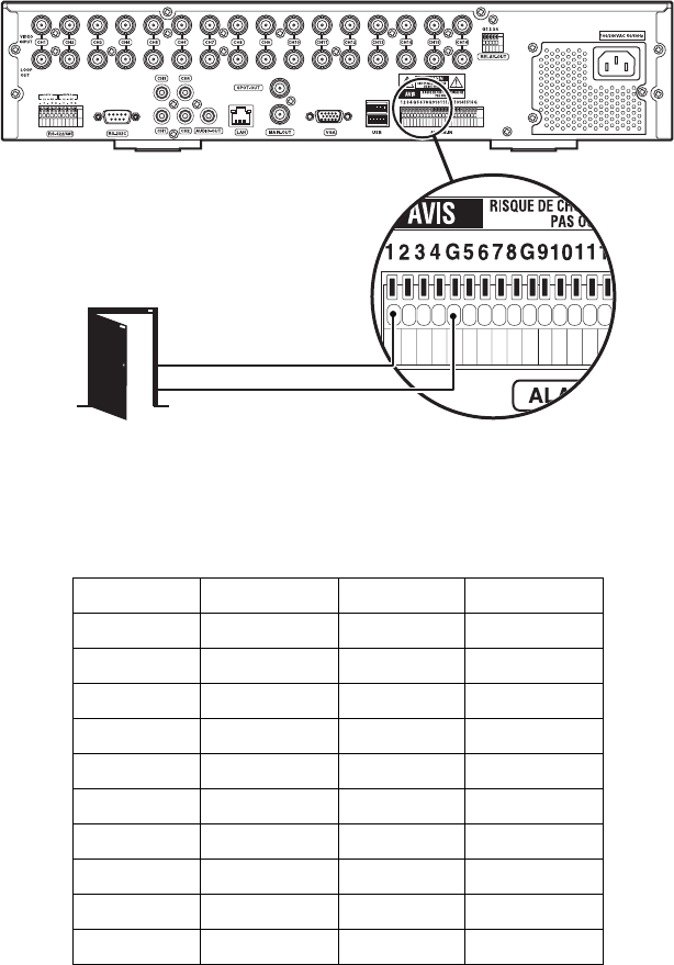
The DX4500/DX4600 provides a numbered terminal block for connecting alarm devices. Alarms are programmed for normally open or normally
closed inputs. Eight-channel DVRs support up to 8 alarm devices; 16-channel DVRs support up to 16 alarm devices. For information about
configuring the alarm inputs, refer to the DX4500/DX4600 Operation/Configuration manual.
1. Using a small screwdriver (or similar tool), push in one of the alarm terminal block wire retainers (1 to 4, 5 to 8, 9 to 12, or 14 to 16).
2. Connect one wire from the alarm device to the receptacle of the depressed retainer, and then release the retainer.
3. Push in one of the alarm ground terminal block retainers.
4. Connect the second wire from the alarm device to the ground receptacle.
5. Repeat steps 1 through 4 for any additional alarm devices to be connected to the DVR.
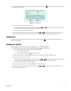
Figure 10. Connecting Alarm Devices
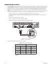
The following table describes pinouts for the alarm terminal block.
Table F. Alarm Terminal Block Description
Terminal Alarm Input Terminal Alarm Input
1199
2 2 10 10
3 3 11 11
4 4 12 12
G Ground G Ground
551313
661414
771515
881616
G Ground G Ground