


18 C1552M-C (7/07)
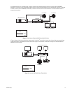
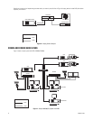
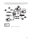
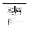
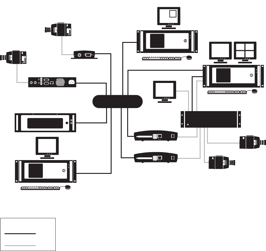
In Figure 12, PelcoNets 1 and 2 encode video from Cameras 1 and 2 respectively for transmission over the network. PelcoNets 3 and 4 encode
video from Cameras 3 and 4 using the switchers looping outputs. This allows the video to be displayed on Client 1 and recorded on the NVR.
The NVR also records video from Cameras 1 and 2. VMX300(-E) Client 1 displays IP video from all four cameras. Client 2 displays IP video from
Cameras 1 and 2 and analog video from Cameras 3 and 4. The external monitor displays analog video from Cameras 3 and 4.
Figure 12. Example 3 of a PelcoNet Configuration
VMX SERVER
PELCONET 3
PELCONET 2
VMX CLIENT 1
EXTERNAL MONITOR
CAMERA 1
MATRIX SWITCHER
CAMERA 3
NVR
CAMERA 4
PELCONET 4
VMX CLIENT 2
PELCONET 1
CAMERA 2
NETWORK
LEGEND
DATA
VIDEO