


40 C1552M-C (7/07)
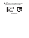
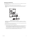
SERIAL OUTPUT DEVICE
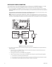
Connect a serial output device to the VMX300(-E) using either a direct serial connection or an Internet Protocol connection. Refer to Figure 24 on
page 27 for a sample direct serial connection or to Figure 26 on page 28 for a sample Internet Protocol connection.
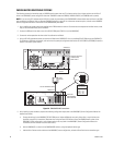
After installing system hardware, complete the following configuration steps:
1. Add the Serial Output driver and the serial output device to the VMX300(-E) server configuration (refer to the VMX300(-E) Server
Configuration Manual for instructions).
2. Change the serial output device settings to match the VMX300(-E) COM port: RS-232, 9600 baud, odd parity, 8 data bits, 1 stop bit (refer to
the appropriate device manual for instructions).
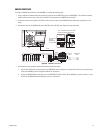
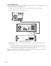
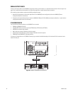
IP-BASED DEVICES
You can connect the following devices to the VMX300(-E) over a network:
• DX8000 and DX9000 Series DVRs
• PelcoNet MPEG Series transmission systems (NET300 Series, NET350 Series, NET4001A)
• NVR300 Series network video recorders
• Matrix switchers (through a PelcoNet transmission system)
• Spectra/Esprit camera positioning systems (through a PelcoNet transmission system)
• CM9760-ALM and CM9760-REL input/output devices
To connect an IP-based device to a 10/100BaseT network, plug a standard unshielded twisted pair Cat5 cable with RJ-45 connectors into the
device’s Ethernet port.
Figure 38. Sample IP-Based Device Connection
NETWORK
VideoIn VideoOut
AudioOut
AudioIn
COM1:RS232/485 10/100Base-T
Ethernet
Power
100-250VAC50/60Hz100mA
COM2:RS232