


C1552M-C (7/07) 33
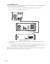
CM6700 SWITCHER
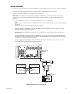
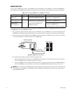
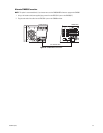
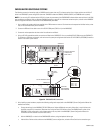
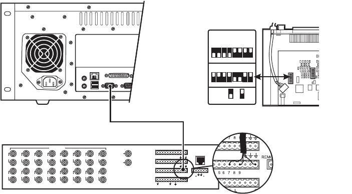
To connect a CM6700 switcher directly to the VMX300(-E), complete the following steps:
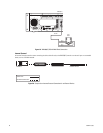
1. Using a modified null modem cable (user-supplied), plug one end into the DB9 COM 1 port on the VMX300(-E). The modified null modem
cable should be cut at one end, so that you can connect the wires directly to the CM6700 screw terminals.
2. Connect the other end of the cable to the COM 2 screw terminal connector on the CM6700 switcher. Note the pin assignments on the
wiring.
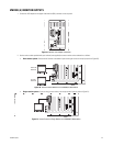
3. Remove the cover from the CM6700 and set the SW5 DIP switch to RS-232 mode. Replace the cover when done.
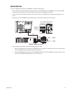
Figure 31. CM6700 Connections
4. After installing system hardware, complete the following configuration steps:
a. Add the Pelco ASCII driver and the switcher to the VMX300(-E) server configuration, and select Direct Serial as the connection type
(refer to the VMX300(-E) Server Configuration Manual for instructions).
b. Change the CM6700 COM port settings to match the VMX300(-E) COM port: ASCII, RS-232, 9600 baud, no parity, 8 data bits, 1 stop
bit (refer to the CM6700 Installation/Operation manual for instructions).
13579
246810
11
12 14
13 15
16
1
2
VIDEOINPUTS
VIDEOOUTPUTS
ALARMS
(1-9)
ALARMS
(10-18)
COM1(1-6)
COM2(7-12)
CONTROL
OUTPUTS
REMOTEKEYBOARD(S)
LOCAL
KEYBOARD
123456789
10
11
12131415161718
12345678910
11
12
0123
F
2
F
3
N
O
N
C
C
O
M
TT RR
+ +
12345678
ON
12345678
ON
RS-422/485
ON OFF
KEY
RS-232
SW5DIPSWITCHSETTINGS
1415161718
10
11
12
F
NN
T
COM 1 OR
COM 2
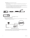
2 RX............................
3 TX...........................
5 GND.....................
CM6700-MXB
COM 2
7 TX
12 RX
9 GND
RS-232
CM6700
NOTE: TO PROPERLY SHIELD DATA CABLE
CONNECT GROUND ON ONE END ONLY.
SET DIP SWITCH
(SW5) ON
CM6700-MXB
TO RS-232 MODE