


34 C1552M-C (7/07)
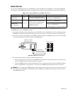
CM6800 SWITCHER
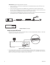
You can connect a CM6800 switcher directly to the VMX300(-E), using the DB9 COM port on the VMX300(-E). The recommended CM6800 port
varies, depending on the CM6800 switcher model and configuration. Table J provides a port recommendation for each model or configuration.
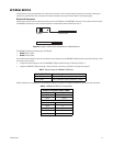
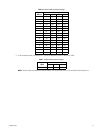
Table J. Recommended CM6800 Port for VMX300(-E) Connection
*If you prefer to use the on-screen programming menus to program your CM6800 system (instead of the CM6800-MGR software), you can use
the CM6800 COM 1 port for the VMX300(-E) connection.
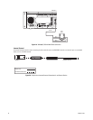
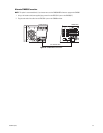
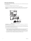
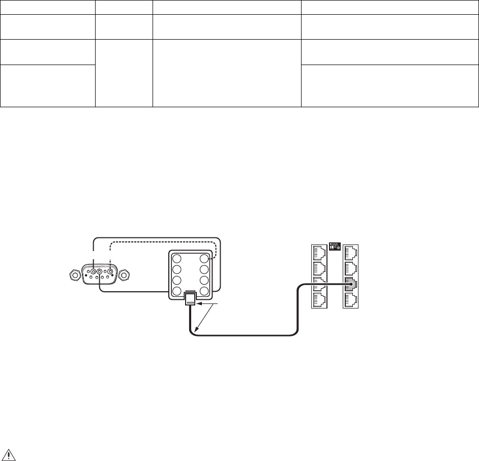
1. Using a modified null modem cable (user-supplied), connect the DB9 COM 1 port on the VMX300(-E) to an RJ-45 wall block (supplied with
the CM6800). The modified null modem cable should be cut at one end, so that you can connect the wires directly to the wall block pins.
2. Using a 6-foot (1.8 m) data cable (supplied with the CM6800), connect the wall block to the CM6800, using one of the RJ-45 ports (COM 2,
7, or 8; note that COM ports 7 and 8 are not available on the CM6800-32X6).
)
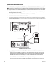
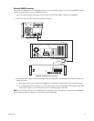
Figure 32. CM6800 RJ-45 Connections
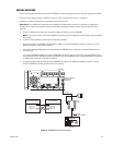
3. After installing system hardware, complete the following configuration steps:
a. Add the Pelco ASCII driver and the switcher to the VMX300(-E) server configuration, and select Direct Serial as the connection type
(refer to the VMX300(-E) Server Configuration Manual for instructions).
b. If you use a CM6800 port other than the port recommended in Table J, change the port settings to match the VMX300(-E) COM port:
ASCII, RS-232, 9600 baud, no parity, 8 data bits, 1 stop bit (refer to the CM6800 Installation/Operation manual for instructions.
Model/Configuration CM6800 Port CM6800 Port Programming Recommended allocation of other COM ports
CM6800-32X6 COM 2
COM 2 default settings match the settings
required for the VMX300(-E) connection.
Reserve COM 1 for CM6800-MGR PC*
CM6800E-48X8:
48 x 8 configuration
COM 7 or 8
Change the COM 7 or COM 8 port type to
RS-232. The remaining default settings
match the settings required for the
VMX300(-E) connection.
Reserve COM 1 for CM6800-MGR PC*
CM6800E-48X8:
96 x 16 configuration
Reserve the following ports:
• COM 1 for CM6800-MGR PC*
• COM 2 for the 96 x 16 “bay-to-bay” connection
WARNING: If you use alarms in the CM6800 switcher, configure the alarm settings so that no alarms are sent to the monitor output used
for the connection to the VMX300(-E). If the VMX300(-E) receives a CM6800 alarm, VMX300(-E) system operators are not able to view or
control CM6800 video streams.
3
4
5
6
7
8
CM6800-48X8 COM 7
RJ-45 WALL BLOCK
AND STRAIGHT CABLE
SUPPLIED WITH CM6800
MODIFIED NULL MODEM
CABLE (USER-SUPPLIED)
1
2
VMX300/VMX300-E
1
2
3
4
7
6
5
8