


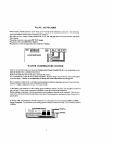
VALVE
ACTUATORS
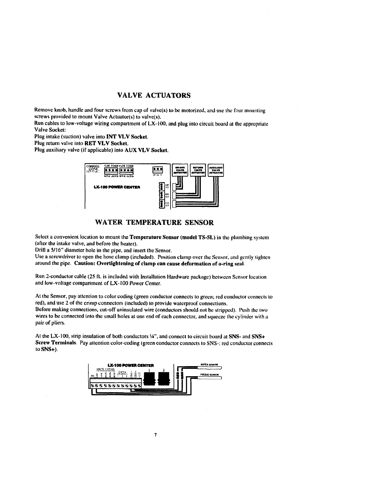
Reniovc knob, handle and four $crew?; from
c;ip
of
valvc(r)
to
bc matorixcd,
and
rase
thc
four
mounting
screws
provided to mount Valve Actuntods) to valve(s).
Run cables to low-voltage
wiring
uompartn~ent of
LX-
100,
ond
plug into circnit board
at
thc uppropriatc
Valve Socket:
Plug
intake (suction) vslva into
INT
VLV
Socket.
Plug return valve inta
RET
VLV
Socket.
Plug auxiliary valvc (if applicable) inta
AUX
VLV
Socket.
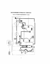
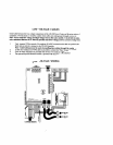
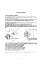
WATER
TEMPERATURE
SENSOR
Select
a
convenient location to mount thc
Temperature
Sensor
(model
TS-51,)
in ihc plumbing syarcni
(after
the
intake
valve, and
before
the hcatur).
Drill
r
5/16"
diamelcr
hole
in
ihc
pipe, irnd insert the Sensor.
Use
n
screwdriver to open
the
hose cln~i~p (includrtl). Posi~ion clamp
over
the Senaar, antl
gcntly
tighten
around
the
pipe.
Caution:
Ovcrtightening
of
clamp
can
cause
deformation
uf
u-ring
sci~l.
Run
2-conductor
cable
(25
R.
ix
included with Inslallrbtian Hardware package) between Scnsor Iociition
md low-vollagc conlpartmcnt
of
LX-
100
Power Center.
At the Sensor, p;ay atlcntion
to
color coding (green caiiductor connccts lo grecn; red conductor connecls lo
red), and
use
2
of
the cnnrp connectors (inclutlcd)
to
provide wl~crpmol'connectionu,
Bcfore making connectic~ns, c~~l-orf uninsultrted
wire
(conductors sl~or~ltl
not
be
s!
ripped). I'r15h the
twu
wires
to
be
connected into the small holes at one end
of
each
conncctor, and squeczc the cy li11dr.r
with
;I
pair
of pliers.
At the
LX-100,
strip insula~ion
of
both conductors
$5".
and connect
to
circuit board
81
SNS-
and
SNS+
Screw
Terminals.
Pay attention color-coding (green conductor connects to
SNS-;
red conductor connects
to
SNS+).