


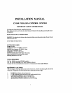
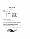
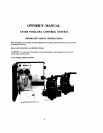

CP-100
INDOOR CONTROLLER
Select
iI
cunvc~rictil lecatiun irraidu the house or athcr weather-protcctcd area to nlount the CP-I00 Con~rul-
Irr.
The
overall wiclth of tlic Controller {with doors open)
is
I
I
-W.
The locarior~ of the 6-conductor coni-
munic:~tion cables (on thr cunterline of the enclosure) shoultl thcrcfore
bc?
at
least
5-'A"
fro111
any
door
jamb,
wnll corncr or other oblrti~cle.
Remove bilckplatc from Controller. Temporarily pull cables through large hole In hrekplate, and position
backplate
on
surface of wall, Make
sure
that backplutc
is
level and that
''TOP
nomenclature
is
oriented
comctly, und mark the thrw rnounling points on the surfiice of the wall. With the backplate removed from
the wall. drill 3/16"
diilrneter holes and insert mountiog anchors (included) into
the
three holes. Pull cables
through lurgc hole in hnckplate, and use the three
14"
screws
to
mount
backplate to wall.
Use the
Crimping Tool (model
'TOOL-6)
to attnch modular conncctoa at each end of both cables. See
1ISING
THE
CRIMPING
'~O'OOL.,
below,
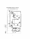
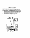
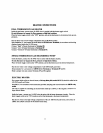
At the CP-100 Contmlter, plug the kilccr cable (with modulitrconllcctar attached) into the circuit board at
Socket
#I
(SII,VI?H),
and plug the black cable into
Socket#Z,
Use ttrc f~~trr
W
screw> (included)
lo
srotlnt
CP-
100 Controller to the bickplate.
At the
1.X-
100 Power Ccntcr, plug the silver cable (with n~oduliw connector attached) into the circuit bond
31
Socket
#I
(SLLVER).
;~nd
plt~g the black cable into
Socket
#2.
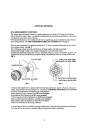
USING
THE
CRlMPlNC
TOOL
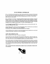
Make sure thilt the end of the cnhle
is
cut squsmly (not diagonully).
Insert thc cable hetwccn the
stripper
hlades of the tool until it touche$ thc stop, Squeem the handles and
prrll the tool, maklng sure ihiit the cable stays perprndiclrlar
to
i~.
If
this
is
done correctly, the outer jnclct
of
the cubic will hc re~novcd withsi~t damaging the insirlation
on
the individual condtictors.
Pl;tcc a nrudt~lur connccror in
ihr
tloldcr portion
of
the tool
so
that the fron~ of the connector is against the
\top
and the
gold
co~ltucts bcc
the
crimper. Oricnt thu pwparcd cable so that the
blue
conductor
is
closcsb
to the tool liantllcs. :tnti insen cable into connector. Make certi~in that the conductors
are
tlush with Lhe tip
of
tltc connector and di~ctly under the gold contacts.
Squeeze
thc hancllcs
firmly
to set the contacts
i~nd
wcurc
tlir
cuhlc,
Note:
It
is
important
that
thc! orientation
(blue
conductor
closest
to
tool
handles)
is
identical
at
all
four
cable
cnds.