SYSTEM START-UP
s rtem.
Apply power to th~
y
At
the Power Center, verify that the
POWER ON
sbtus
light is illu~ninated, and make sun: that
;ill
of
thc
Service Switches
are in the
"AUTO"
position.
If
the stitlus light is not
on,
check the
J
wrnp circuit brcokcr which is located
abavc
!he faceplate. If the cir-
cuit
breaker has tripped
(indicated
by
i\
white tab), push to rcsct.
At
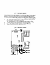
the Indoor Controller, verify that there is
a
TEMPERATURE Display
and check Ihi~l rhc
EQIIIP-
MENT STATUS INDICATORS
are functioning when the
IDushbuttons
are activated.
Irtheru
is
no status display, check the connections at each end of the communication cables very carefully.
If
necessary, crimp new modular connectors to the cables.
If
the TEMPERATURE Display
indicates three dashes
(-
-
-)
ar
a
very high temperature
(400
dcgrces or
more), check tho connections to the Temperature Sensor,
At the Indoor
Controller,
press irppropriate
Pwhbuttonfs)
so
~hnt
none of the
EQUIIDMENT STATUS
1NDlCATORS
arc illuminated.
At
the intake and Rclurn
Vrrlvcs,
Flip
toggle switch on rear of A~Iui~tor(s) between
"ONI"
i~nd
"ON2"
positions as nicessary so that volvcs have
rotated
to pool circul;itinn.
At
the Power Center, ver~fy [hut tho
FILTER
PUMP
Time
Clock
is operitting.
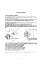
To set the time of day, rotatc the dial in
a
clockwisc directiorr until the hours
irnd
~ni~~utes line up w~th
the
white amow at eight o'clock position
on
clock face.
To
progmrn daily opcrzlting cycle(s), depress the desired numbcr of sections around the perilnt.,
r~l
ll~c
dial
by
pushing towards the center. For each section depressed,
the
filter pump will oporute for
15
roinules.
If
the system lias
a
POOL
CLEANER
Timc
Clock,
verify that it
is
operating, and check thi~t it also act!-
vates the filter pu~rip whcn the
FILTER
PLJMP
Timc
Clock
is not programmed
on.
At the Power Center,
slidc
the
SPA
Service
Switch
to
"FILL.
"1)KAIN" and hack
to
"AIlTO"
posrlion,
and verify that the Valvc Actuators arc? rotating accordingly.
If
one of the Valve Actuators is
180
degrees
out
of phase, flip toggle switch
on
rear of Acltiator bctwcen
"ON1
"
and
"UN2"
position,
At
the Power Center, verify thirt the filter pump
is
being activated from the
"QN"
i~nd
"OFF"
posltlons
or
the
FILTER
Service
Switch.
Verify that
thc auxiliary equipment is being activated fmm the
"ON"
and
"OFF'
posi~ionu oi' the
AUXI,
AUX2
and
AUX3
Service
Switches.
Slide
FlLTER
Scrvica
Switch
to the
"ON"
position and the
HEATER
Service
Switch
to thc
"SPA
X!
POOL"
position, and ver~fy that thc hratzr hiis fired.
If the
heatcr doesn't
fin..
check the controls inside the healer and also the
wiring
conrtvctions.


