


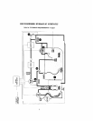
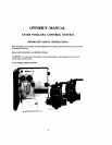

Select a col~venient location to mount the LX-100 Power Center. Ensure
ht
the location is
greikr
than
5
frrt from the water's
edge
and no hurther than
15
feet from any motorized valves (otherwise Valve Actua-
tor cables will need
lo be extended).
Mount the
1.X-100
on
a
flat surface using appropriate screws lhrough the three cxtenlal mounting paints
located on the side
of
the enclosure,
Do
not
drill
and
mount
from
inside
the
enclosure.
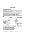
Looscn LOCK
SCREW
of hinged faceplate in left-side of
LX-100,
and
swing open to expose the low-volt-
age
compirtment. All low-voltage connections
are
made to the circuit board, in accordance with wiring
diagram
lucated inside door.
The
high-vottage wiring compnrtment is located behind service panel in right-side of LX-100.
HIGH
VOLTAGE
WIRING
GENERAI,
At khe equip~nent site, install
an
electrical sub-panel wbh separate breakers
for
each load,
Circuit breakers should
be
readily accessible to the spa user, but installed at least
5
feet froin
the
water's
cdgu.
Make
sure that the rnolor(s) on the equipment have built-in thermal protection.
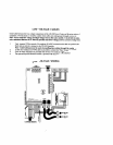
At the
LX-100, remove the
service
panel (at left) to expose the high-voltage compariment,
and
knock-out
the
appropriate
l~oles
at
bottom of enclosure to facilitate condui~ mounting. Screw terminals are pmvidcd
for high-voltage corrncctions.
SYSTEM POWER
Provide
a
repiirate circuit b~aker to power the system. Either
1
15
or
23OVAC
cnn
be
used
[
I
15V
is
pref-
erable). System dnws less than I-Amp. The breaker will
open
all ungrounded supply conductors to com-
ply with section
422-20
of
the National
Electrical
Code, ANSVNFPA 70-1987.
Run
approprialo
wires
from circuit breaker to high-voltage compartment of LX-100, and connect to top
renninal black in iiccordince wilh wiring label, which
is
marked
SYSTEM
IDOWER,
Install two jumper wires for
11
SV,
or one jumper for
230V,
according to
wiring
label.
EQUIPMENT
POWER
Provide independent circuit breakers for
R1
(FLTR),
It2
(AUXI),
TW
(AUX2) and
R4
(AUX3).
Run opproprii~te wires from breiers to high-voltage compartlnent of LX-100. and connect to LINE1 and
LINE2
sscrcw
terminals at each terminal block.
Connect pumps and other high-voltage equipment
10
LOAD1
and
LOAD2 terminals.
Each individual terminal
block can
be
wircd for eithcr
115V
or 230VAC.
Note: For
11
5V
cquiprnent. only half of the terminal block will
bt.
used
(ic:
LINE1
rmd
LOADI).