


PLUlVIBING
REQUIREMENTS
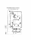
Plumb system in accordance
with
"RECOMMENDED
HYDRAULIC
SCHEMATIC"
on
page
2,
lmal
cdes und the following guidelines.
Bring
all lines back to the equip~nent pad.
1.
Spa
should
be
at
or
above
the level of
the
pool.
If
spa
is attached
to
pool, provide a dam bctwcen the bwo bodies of wilter to allow spa overflow
into pool,
If
spa
is
not attached to pwl, an overflow. sufficient in size to carry
full
pump-flow,
must
bt:
installed at water level
in
tlie
spa.
2.
Plurnh a three-port Intake
Valve
on the suction-side ol the filter pump, so that cearer port of vnlvr
is connected to the pu111p inlet.
Connect spa suction to
one
side
of Intake Valve, and pool suction to the othcr side.
3.
Plurnh
a
three-port
Return
Valve
on the return-side
of
the heater, so tllot rcturt~ walcr
will
cnlcr
valve through the center pon,
Conncct spa return to one side of Return Valve, and pool return to the other side.
4.
A
W
spa make-up line (incot-prating
a
H"
manual gate or ball valve and, for elevated spis, a
'/I".
check'valvc) may
bc
provided to bypass the pool return line. l'his will enable some al the chemi-
cally-balanced water from
the
pool to cycle through die
spa.
The manual valve will allow lhe
amount of bypas to
be
adjusted,
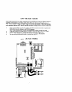
5.
If
the spa is to
be
constructed in concrete, special provision should
be
made ut this time for the.
installation of
the
Spa-side
Remote Control.
Select
n
convenient location
in
the deck or above water level in the spa wall (where the Spa-side
Ru~nore will not
be
submerged by the
spa
water). and install
n
6"
to
12"
length
of
I-'/)'"
pvc pipe to
pmvide
r
receptacle for the
Spa-side
Reniorc.
The
pipe should be level and protrude beyond
the
finished surfilcc of the
spa.
It
will
be
cut
back
n
later date.
Reduce pip size down to
$5''
or
%iV
conduit, and run to proposed
LX-IOU
location at equipment
pad.
Use
swcep elbows for turns.
The
Spa-ride
Remote wlll not
be
installed
until
spa
construction
is
iwmplclc.
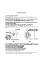
6.
For systems which incorporate
a
skimmer.
it
is possible to balance
the
amount of suction between
the skimmer and main drain for maintenance purposes.
This
is
uasily accomplished
by
installing a manual three-port mixing valve at the suction linc.
Plumb
onc port to the skimmer and the other to the main dnin.
7.
If
a
"non-booster pun~p" pressure-side pool cleaner
is
being used, plumb
a
manual three-port valve
between the filter pump and filter, with the
third
port plumbed
to
the pool cleaner linc. and install
a
motorized two-porz Pool Cleaner
Vaive
at this line. The motorized valve
will
autr~~natically open
wl~encvcr tlie Control System activates
Ihe
pool
clmna.
8.
If a booster pump pool cleaner
is
being used. plumb the booster pump
so
that its suction-side
is
connected to
the
pool return, after the heater
and
as
close
to
the ground
as
praaicnl.