


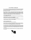

POOL
CLEANER
For
sy~tctii~ wlllch i~icorporirte
iI
hnoarcr pump p(~ol cleaner.
il
is
posbibls
to
ildd
a
~nech;rnic;~l tiliic clock
for prugrunitnlag the di~ily dlcunil~g cyclch,
Inatall
24-flour Time Clock
{model
TMH-1.X)
lnre LX- 100 f;~ceplnte nt the
POOI,
C1,EANER
locat~on,
and plug rntu top
of
circuit
boild ikt
CLNH
TIMER
socket,
In accordance with instnlctions prov~dcd,
1nat;:H
D
20-Amp
Relay
Kit
(model RLY-LX)
at the LX-100 Power Center in woordanre with instruc-
11uns provided, und plug Into cIrcirIt board
CLNR relay sockcl.
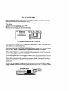
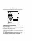
AUX1LIAHY
VALVE
It
is
prr\sihle
to
t~dd
il
Valve Actuator (model
CVA-24)
to
rhc system to motorize
a
two-port
or three-port
vnlvr: for
it
cualom hydraulic feetun. (silch ils
n
pool clermer, fountain, waterfall. etc.). The Valve
Actuator
C~II
hc
il~ttvi~tctl rrt.\~lt eithcr the pool cleilncr or ituxiliary
3
circuit.
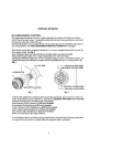
Ktmuve knob, handle slid four screws rrorn cap of valve
to
he
motorized, and use the Ibur moilnling
\crew* prouidcct lo stollnt Velvc Actuator to valve. Run cabk to low-voltage compartnicnt
of
LX-100,
and
plug intt9 circuit ho.~rtl
111
AllX
VI,V Valve Socket,
ItIc~iliiy
lll~
I-ptn~ti~ri
AtfX
VI,V
Program
Switch,
whrch
is
located at bottom right
of
L,X-t(H)
circuit
hoiird. i11td
(IN
thc curncr
of
il
ur~iilll
sc.~wdrrv~.r ot other blulit instrument to adjust !lie Swilch accordingly:
I
To
JCI~VJ~C
V;IIVC
in3111
the
pc>o1
clenrier circuit, [urn
Switch
#1
ON
and
Switch
#2
OFF.
2.
'To
;lrtlvatc
valve
fro111 tlrr auxiliary
3
circuit, ltrnr
Switch
#I
OFF
iind
Swltch
#2
ON,
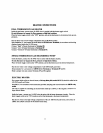
SPA
WA'I'ERYALL
CON'I'HOL,
Itor
systc~iia wlicre spa water Icvel
1s
l~igller that1
that
or the pool, it
is
possiblc
to
use the sl~xiliary
1
circuit
to
roti~te the return vitl~e
to
?iPil return poGtiun.
{hub
crciit~ng
,111
ovcrtlow (watcrf;lll effect) Frt~rn lhe
spa
Infir
the pocrl, This featurc
will
cease
whenevcr the spa
is
being circulnted
7'0
rnnhlc this f~i~tii~, it
is
lacessary lo ~tljust the 7-position
WTHPL-AUXl
I'rognm
Swiith,
which
is
loci~t~d at ccntcr right
of
LX-100 circuit boi~rd. the
the
corner
elf
a
mill
screwtlrivar or otlier blunt
instru-
luc~it to \lrdc
Switch
#I
and
Switch
112
to the
ON
pmition.
FREEZE PROTECTION
A
Rccircubting Freeze
Serrsor
(niodel
FPS-C)
mity
he added lo the system. ft
will
protect thc plr~~nh~ng
.at4
eqt~~pllle~tt h111 ptrxaiblc
frec~e
d;i~ni~gc
hy
runnlng the
filler
pump whenever the ternpereltitc fall\ to
'rpprnr.
J
I
OF.
Insti111
FPS-C
III
uccurd;lncc
I\.
1111
in~rructiun\ provided,
and
connect to LX- 100 circuit
board
at
FRZ
and
GND
+crew
tcniiiltnls.
An Auxiliary
Freeze Sctwor (model
FPS-AUX)
moy
illso
be
iddd
to the
system
t
uctivatc
it~~ili~fy
eqiripnicnt
(\itch
as
a
jct pump) during potent~rtl freez~ng conditions.
Insdl FPS-AUX In ascordirnce with insiructians
provided.
Note: It
is
udvisitblc
to
inspccl and test Freeze Sensors
at
least once
s
year, preferably prior
lo
the
onset
d
thc freezing season. Testing can
be
done by
immersing
Sensor in ice water.