


SYSTEM
OPTIONS
SPA-SIDE
REMOTE
CONTROL
The optional Spa-side Rcmote Control
is
a
double-insula~cd device which
is
UL-listed ror instiillation
within
5
feet of the wuter's
edge.
11
is
typically inslallcd at the tiIe-line of
the
spa wall
(above
wntcr level).
or in
thc
deck within
arm's
reach of thc spa.
If
the
Sp-side
Remote
is
to be installed into the wall of
a
gunite spa, provision should
bc
lnade
while
the
spa
is
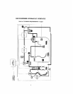
king plumbed. See
"RECOMMENDED
HYDRAULlC SCHEMATIC"
on
page
2.
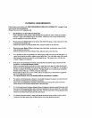
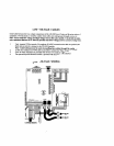
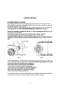
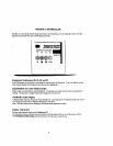
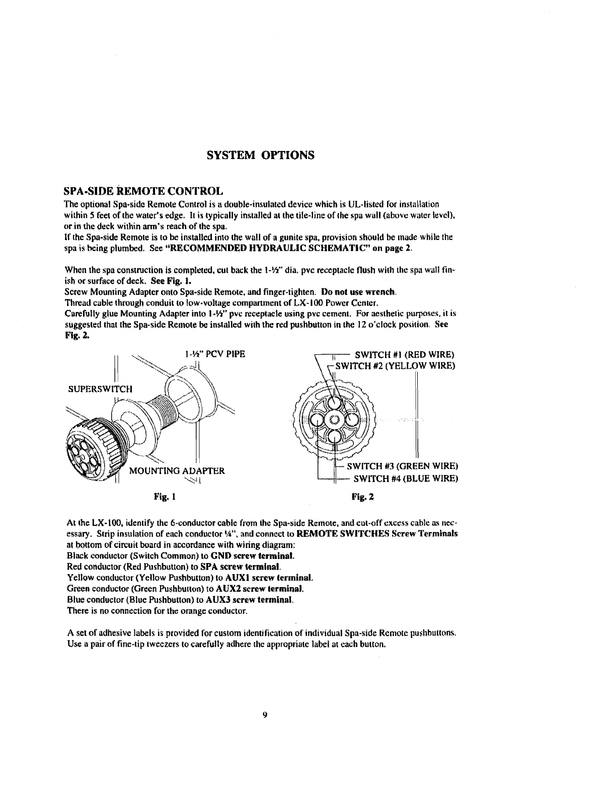
When the spn constmctio~r
is
completed. cut back the
1-55''
dia,
pvc receptacle flush with the
Fpa
wall
fin-
ish
or surface of deck.
See
Fig.
1.
Screw Mounting Adapter onto Spa-side Hemole, and finger-tighten.
Do
not
use
wrench.
Thread cable through conduit to low-voltage compmment
of
LX-
100 Powcr Ccntcr.
Carefully glue Mounting Adapter into
I
-U"
pvc reccptaele using pvc cement.
For
aesthetic purposes,
it
is
suggested that the Spa-side Rcl~tole
be
instiillcd
with the
red
pushbutton
in
the
12
o'clock position.
See
Fig.
2.
I-%"
PCV
PIPE
SWITCH
I11
(RED
WIRE)
H
#2
(YELLOW
WIRE)
SUPERSWITCH
MOUNTING
ADAPTER
M
#3
(GREEN
WIRE)
CH
#4
(BLUE
WIRE)
Fig.
I
Pig.
2
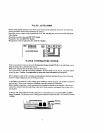
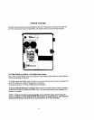
At the
LX-100.
identify
he
6-conductor cahll: from thc Spa-side Remote,
and
cut-off excess cable
as
nec-
essary. Strip insulation
of
ench conductor
',4",
and connect to
REMOTE
SWlTCHES Screw
Terminnls
at bottom of circuit board in accordance with wiring diagram:
Black conductor
(Swilch Common)
LO
GND
screw
terminal.
Red condk~ctor (Red Pushbuttan)
to
SPA
screw
terminal.
Yellow
conductor (Yellow Pushbutton) to
AUXI
scrcw
terminal.
Grecn conductor
(Grrcn
Pushbutton)
to
AUX2
scrtw terminal.
Blue conductor (Blue Pushbutton) to AUX3
scrcw
terminal.
There
is
no connection for the orange conductor.
A
set
of
adhesive labels is provided for custom identification
of
individual Spa-side Reniote pushbuttc~ns.
Use
il
pair nf fine-dp tweezcrs to carefully adhere thc appropriate
label
at
each button.