


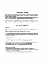

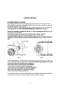
HEATER
CONNECTlONS
DUAL
THERMOSTAT
GAS
HEATER
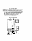
Inside the
gas
heater, connect three
18
AWG
wCrm
in
parallel with the heater toggle switch,
Do
not
dlscunnect
or
bypass
the
flow,
pressure
or
high
IImlt
switches,
Place the heater
toggle
switch in
the
"'OFF'
position, md
set
he thermostats
to
desired
pool
and
spn
tern-
pemtures.
Run he three wires to low-voltage compartment
of
LX-100 Power Center.
Strip
insulation
!A",
and connect to circuit
board
at
GMTR
Screw
Terminals,
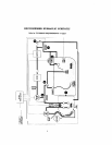
in accordance with wiring
diagram located inside the LX-100 cover:
Connect "High" of heater
thermostat to
Terminal
#S.
Connect "Low" of heater thcnnostat to
Tkrminal
#P.
Connect "Commnn" of heater thermostat to
Terminal
#C.
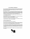
SINGLE
THERMO$TAT
GAS
HEATEmEAT
PUMP
inside
the
heater, connect two 18
AWG
wires in series with the heater circuitry,
Do
not disconnect
or
bypass
the
flow,
pressure
or
hJgh
limit
switch&
Place the heater toggle switch in thc
"ON
position, and set the thermlmttt to the desired temperature.
Run
the two wires to low-voltage compmment of
LX-180
Powerhad Center.
Strip insulation
W,
md
connect
to
GHTR
Screw
'Rrminab
at
Terminals
#P
and
#C.
Make
a
jumper
wire
and
connect Terminds
#P
and
#S
together.
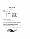
ELECTRIC
HEATER
For systems which utilize
nn
electric heater,
a
20=Amp
Relay
Kit
(model
RLYI,X)
should be udded
at
the
WL-
100
PowerILond Center.
1nst;tll RL-LX in accordonce with instructions provided,
md
plug
onto circuit
hard
at
the
EHTR
relay
socket.
The
relay
is
captrble of controlling an
clecuic
hcatcr (rated up
to
3KVA),
or
the magnetic contactor
of
a
Larger electric heater.
hide
the
heater, connect two 14
AWG
wires
in
series
with
the heater thermostat circuitry. Place the
heater
to~gle switch in the
"'ON"
position,
and
sa
the lhcrmostal to the desired temperature.
Run
the
rwo wirev to the high-voltage compartment of
the
LX-100
Power/Lod Center, and connecr Lo
LINE1
and
LOAD1
terminals of he clectric
heater
relay.