


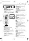

Connecting to a TV
Basic Connections
•
Please refer to the instruction books of your TV, VCR, Stereo
System or other devices as necessary to make the best connections.
• Make one of the following connections,depending on the
capabilities of your existing equipment.
CAUTION:
• Be sure to turn off the VCR/DVD and equipment to be
connected before connecting.
• Read through the operation manual for the equipment to be
connected.
• Be sure to keep the VCR/DVD connection cables separate
from the TV antenna cable when you install the VCR/DVD,
because it may cause electrical interference when you are
watching television programmes.
6
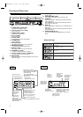
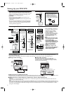
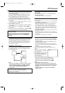
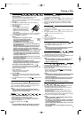
Setting Up your DVD/ VCR
Basic TV Connection
(TV)
AEREAL
RF OUT
RF coaxial cable
(supplied)
To RF OUT
jack
from Antenna
To AERIAL
jack
CAUTION:
• Connect the VCR/DVD directly to
the TV.Do not connect the
VCR/DVD to a VCR,then connect
the VCR to the TV.Copyright
protection in the VCR could distort
the picture playing on the VCR/DVD.
VCR/DVD
VCR
TV
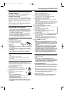
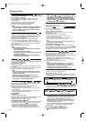
C Analogue audio connection
Digital Connection to an MD to Record a CD
Some Audio CDs have a short silent section between musical tracks.When sound from discs such as these is digitally recorded by connecting the VCR/DVD directly
to a digital recorder (such as an MD recorder),the music may be recorded continuously and track numbers may be lost.
C
Digital Connection to Audio Equipment or MD Recorder without a Dolby Digital Decoder
• Audio CD
Audio CDs can be transferred digitally to other equipment such as an MD recorder,play the disc as you would normally with the audio mode set to
“L+R” and use the connection shown above.
•DVD
DVDs recorded in Dolby Digital multi channel surround sound or MPEG Audio cannot be connected digitally to external recording equipment such as an
MD recorder. The audio source on a disc in a Dolby Digital multi channel surround format cannot be recorded as digital sound by an MD recorder.It may
be possible to record Dolby Digital or MPEG Audio via a digital connection if the VCR/DVD output is set to “OFF” for “DOLBYDIGITAL” or “MPEG”
(see page 18 “Audio Settings”).
ANALOG INPUT
R
L
DIGITAL
AUDIO OUT
COAXIAL
COMPONENT
VIDEO OUT
AUDIO
OUT
S-VIDEO
OUT
DVD
VCR
DVD/VCR
L
L
Y
L
R
R
C
B
/
P
B
C
R
/
P
R
R
AUDIO INAUDIO OUT
VIDEO OUTVIDEO IN
(Red)
(White)
(Red)
(White)
Amplifier of stereo system, etc.
DVD/VCR
Audio cable
(supplied)
Jack and Plug Colours
To amplifier
audio input jacks
Audio Left: White
Audio Right: Red
To A UDIO
OUT jacks
C Digital audio connection
You can make this connection using a coaxial digital cable.
Connecting an amplifier with a Dolby Digital/ MPEG Audio digital
surround processor to your VCR/DVD’s coaxial digital jack provides
richer and more powerful audio play.
DIGITAL IN
COAXIAL
DIGITAL
AUDIO OUT
COAXIAL
COMPONENT
VIDEO OUT
AUDIO
OUT
S-VIDEO
OUT
DVD
VCR
DVD/VCR
L
L
Y
L
R
R
C
B
/
P
B
C
R
/
P
R
R
AUDIO INAUDIO OUT
VIDEO OUTVIDEO IN
DVD/VCR
To COAXIAL
DIGITAL input jack
To COAXIAL
DIGITAL OUT jack
Coaxial digital cable
(commercially available)
Dolby Digital (multi ch)/
MPEG Audio processor or amplifier
Connecting to Audio Equipment
Connecting the VCR/DVD to audio equipment provides normal stereo sound,plus powerful stereo sound enhanced by Dolby Digital multi channel
surround sound and MPEG Audio.
• Digital connection is not possible if the processor or amplifier to which you want to connect does not have an coaxial digital input jack.
• When the VCR/DVD is connected to a
TV using both a VIDEO cable and an S-
VIDEO cable,only the S-VIDEO
connection is enabled (the VIDEO
connection is disabled).
•You will not be able to hear all of the
sound being output by the VCR/DVD if
you use the VIDEO/AUDIO cable
(supplied) to a monaural TV that has
only one AUDIO input jack.
Notes:
– Be sure that the colours of the
jacks and plugs match up when
connecting the cable.
– Connect the VCR/DVD directly
to the TV.If you attempt to view
video on a TV connected via a
VCR,the copy protection
function will scramble the
picture.
– If you want to listen to the
audio through audio equipment,
connect only the S-VIDEO or
VIDEO cable to the TV.
DIGITAL
AUDIO OUT
COAXIAL
COMPONENT
VIDEO OUT
AUDIO
OUT
S-VIDEO
OUT
DVD
VCR
DVD/VCR
L
L
Y
L
R
R
C
B
/
P
B
C
R
/
P
R
R
AUDIO INAUDIO OUT
VIDEO OUTVIDEO IN
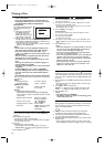
LR
VIDEO OUT
VIDEO IN
AUDIO IN
AUDIO OUT
VCR
DVD/VCR
LL
RR
AUDIO IN
VIDEO OUT
VIDEO IN
AUDIO IN
AUDIO OUT
VCR
DVD/VCR
LL
RR
CB
Y
C
R
COMPONENT
VIDEO IN
PB
Y
P
R
VIDEO IN
S-VIDEO IN
AUDIO
OUT
DVD
S-VIDEO
OUT
COMPONENT
VIDEO OUT
L
R
Y
C
B/
P
B
C
R/
P
R
DIGITAL
AUDIO OUT
COAXIAL
AUDIO
OUT
DVD
S-VIDEO
OUT
L
R
AUDIO
OUT
DVD
S-VIDEO
OUT
COMPONENT
VIDEO OUT
L
R
Y
C
B/
P
B
C
R/
P
R
DVD/VCR
TV
Basic Audio
Video
cable
(supplied)
S-Video
cable
(commercially
available)
(Analog) AUDIO OUT VIDEO OUT S-VIDEO OUT
COMPONENT
VIDEO OUT
Audio cable
(supplied)
DVD only
DVD only DVD only
Good picture Better picture Best picture
Method 1 Method 2 Method 3
Component
Video cable
(commercially
available)
or
or
E8B23AD_EN 5/16/06 12:03 PM Page 6