


10
PHILIPS LTC3963/61 (E) QR31808
EXTERNAL CONNECTIONS
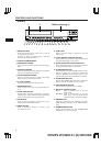
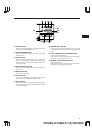
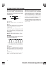
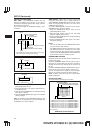
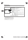
ALARM (A) IN/ ALARM B IN
You can connect two devices including an alarm
switch with a resistance of 1 kohm or less or a door
sensor. Connect pin q or u to pin !5 (ground)
through the switches.
Notes:
• Do not apply a voltage to pin q, u or !5.
• If an alarm is input to the ALARM (A) IN terminal
when an alarm is being input to ALARM B IN, the
input at ALARM (A) IN has priority. However, an
alarm at ALARM B IN is not accepted when an
alarm is being input to ALARM (A) IN.
• The recording conditions are different for the
alarms input to the ALARM (A) IN and ALARM B
IN terminals. See page 19 for details.
ALARM OUT
Approx. 12V is applied to pin w during an alarm
recording.
Notes:
• When you have selected “PULSE” in the “ALARM
OUT” menu in the ALARM display, approx. 12V
pulses will be applied to the output after the
alarm recording ends.
• When you have selected “DURATION” in the
“ALARM OUT” menu in the ALARM display, no
voltage is applied after the alarm recording ends.
• The output impedance is approx. 100 ohm.
ONE SHOT IN
One shot recording is possible when pin e is
shorted to pin !5.
Note: Do not apply a voltage to pin e or !5.
TAPE END OUT
Approx. 12V is applied to pin r when the tape
reaches the end.
Notes:
• This does not operate when you have selected
“REWIND, RE-REC” in the “RECYCLE FUNC-
TIONS” menu in the ALARM display or you have
selected “REWIND, STOP IF ALARM” and no
alarm recording has been made.
• The output impedance is approx. 100 ohm.
TAPE END RESET
The TAPE END OUT can be turned off when pin t is
shorted to pin !5.
Note: Do not apply a voltage to pin t or !5.
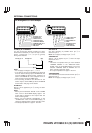
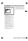
Pin Arrangement of 15-Pin Adapter
q ALARM (A) IN
w ALARM OUT
e ONE SHOT IN
r TAPE END OUT
t TAPE END RESET
o CAMERA SW OUT
!0 REC START IN
!1 REC OUT
!2 LOW TAPE OUT
!3 REMOTE IN
!4 REC CHECK IN
!5 GND
y WARNING OUT
u ALARM B IN
i TIME ADJUST
1110954321
87615141312
ALARM (A) IN ALARM B IN GND
qu !5