


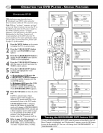
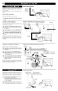
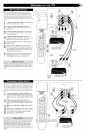

_o e TV s audio/video input jacks are Jbr direct picture and
und connections between the TV and a VCR (or similar
device) that has audio/video output .jacks. Both the AV1 and AV2
Input Jack connections are shown on this page, but either one can
be connected alone. Follow the easy steps below to connect your
accessory device to the AV1 and AV2 in ,lacks h)cated on the back of
the TV
Connect the VIDEO (yellow) cable to the VIDEO AV1 in
(or AV2 in) jack on the back of the TV,
Connect the AUDIO (red and white) cables to the
AUDIO (left and right) AV1 in (or AV2 in) jacks on the
rear of the TV,
Connect the VIDEO (yellow) cable to the VIDEO OUT
jack on the back of the VCR (either one or two) or acces-
sory device being used.
Connect the AUDIO (red and white) cables to the
AUDIO (left and right) OUT jacks on the rear of the VCR
(either one or two) or accessory device being used.
Turn the VCR (either one or two) or accessory device
and the TV ON.
Press the CH + or - buttons on the remote control to
select the AV 1 channel for accessory device number one, or
the AV2 channel for accessory device number two, AVI or
AV2 will appear in the upper left comer on the TV screen
depending on the channel chosen.
With either of the VCRs (or accessory devices) ON and a
prerecorded tape (CD, DVD, etc.) inserted, press the
PLAY button to view the tape on the television.
Note: The Audio/Video cables needed for this connection are
not supplied with your TV. Please contact your dealer or Philips
at 800-531-0039 for information about purchasing the needed
cables.
%0 0 ®
0000
OGO
@®®
®@®
@®®
®®O
ANT75QY in Av2in
VIDEO
L/Mono
AUDIO
i R
AVI
Connection
VCR ONE (or accessoI_2 device)
{ (EQUIPPED WITH VIDEO AND
AUDIO OUTPUT JACKS)
AV2
AUDIO IN
Connection (RED/WHtl
@
ANT/CABLE R L VIDEO
AUDIO OUT OUT
BACK
OF TV
S VIDEO
VIDEO IN
(YELLOW)
VCR TWO toraccessor
(EQUIPPED WITH VIDE
AUDIO OUTPUT JACKS)
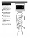
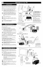
Component Video inputs provide for the highest possible color
and picture resolution in the playback of digital signal source
material, such as with DVD players. The color difference signals
(Pb, Pr) and the luminance (Y) signal are connected and received
separately, which allows fi)r improved color bandwidth #¢brma-
tion (not possible when using composite video or S-Video connec-
tions).
Connect the Component (Y, Pb, Pr) Video OUT jacks
from the DVD player (or similar device) to the (Y, Pb, Pr)
in(put) jacks on the TV. When using the Component Video
Inputs, it is best not to connect a signal to the AVI in Video
Jack.
Connect the red and white AUDIO CABLES to the
Audio (left and right) output jacks on the rear of the acces-
sory device to the Audio (L and R) AVI in Input Jacks on
the TV.
Turn the TV and the DVD (or digital accessory device)
ON.
Press the CH +, - buttons to scroll the available channels
until CVI appears in the upper left comer of the TV screen.
Insert a DVD disc into the DVD player and press the
PLAY _- button on the DVD Player.
w
The description for the component video connectors may differ
depending on the DVD player or accessory digital source equip-
ment used (for example, Y, Pb, Pr; Y, B-Y, R-Y; Y, Cr, Cb).
Although abbreviations and terms may vary, the letters b and r
stand for the blue and red color component signal connectors,
and Y indicates the luminance signal. Refer to your DVD or
digital accessory owner's manual for definitions and connection
details.
CVI
ANT75_qF
@
SteEp
0 0 ®
0000
0@0
The CVI colmeclion will be dominate over the AVI in Video Input.
When a Componenl Video Device is connected as described, it is best
nol to have a video signal connected Io the AV I in Video Input jack.
BACK OFTV
ACCESSORY DEVICE
EQUIPPED WITH COMPONENT
VIDEO OUTPUTS.
S.VIDEO