Connections & Setup
18 Chapter 1
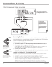
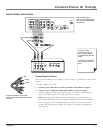
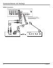
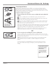
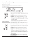
Explanation of Jacks
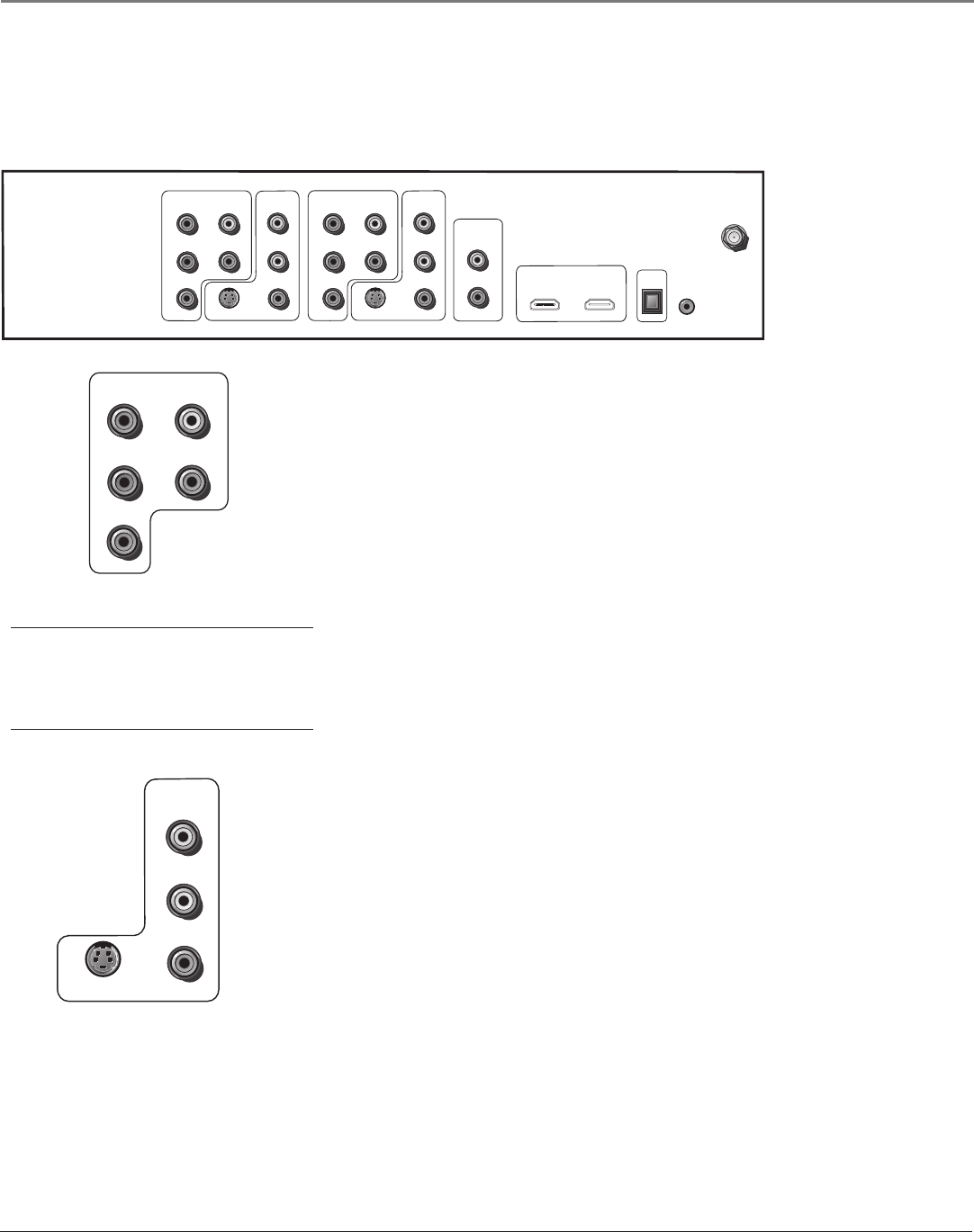
The diagrams below illustrate jacks found on the back of the TV. When connecting cables, be
sure to connect corresponding outputs and inputs (video input into video output, right audio
input into right audio output, etc.).
INPUT 1 and 3 COMPONENT/COMPOSITE INPUTS Provides connection to an
(analog) video device with either composite or component outputs such as a VCR
or DVD player.
• R Audio provides right audio connection and connector is usually red.
• L Audio provides left audio connection and connector is usually white.
• Y/Video P
B
P
R
Unlike a single video input, component (Y P
B
P
R
) video
maintains the video signal as three separate parts through these three jacks.
To ensure maximum picture quality, use three video cables or component
video cables for the Y P
B
P
R
connections. Accepts 480i, 480p, 720p, and 1080i
signals. If you’re connecting to a device with a Video jack instead, you can
still use the Y/Video jack.
Note: Also, remember to connect the left and right audio cables because the
Y, Pb, Pr cables carry only the picture signal, not the sound.
INPUT 3 COMPONENT/COMPOSITE INPUT Provides connection to an
additional optional video device, such as a DVD player or satellite receiver. The
jacks are the same as described above for INPUT 1.
INPUT 2 and 4 COMPOSITE INPUTS Connect an NTSC (analog) device. These
jacks are used for most audio/video connections between devices. The audio/
video jacks are often color coded (yellow for video, red for right audio, and white
for left audio).
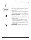
• R Audio provides right audio connection and connector is usually red.
• L Audio provides left audio connection and connector is usually white.
• V (Video) provides composite video connection and connector is usually
yellow.
• S-VIDEO Lets you connect an S-Video cable for better picture quality to a
device with S-Video capability, such as a VCR or DVD player. The S-Video
jack provides better picture quality than the composite video jacks because
the color part of the signal is separated from the black and white part of the
picture.
When using S-Video, make sure to connect the two audio cables as well as
the S-Video connector.
INPUT 4 COMPOSITE INPUT Provides connection to an additional optional
video device, such as a DVD player or satellite receiver. The jacks are the same as
described above for INPUT 2.
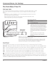
Tip
Inputs 1 and 3 can be used as either component
video (Y PB PR ) inputs or composite video
(Y/Video) inputs.
INPUT 1
COMPONENT/COMPOSITE
Y/VIDEO
PB
PR
L
R
For Factory
use only
INPUT 2
COMPOSITE
VIDEO
L
R
INPUT 1
COMPONENT/COMPOSITE
Y/VIDEO
PB
PR
L
S-VIDEO
L
R
DIGITAL
AUDIO
OUTPUT
VIDEO
L
R
Y/VIDEO
PB
PR
L
R
S-VIDEO
INPUT 3
COMPONENT/COMPOSITE
INPUT 4
COMPOSITE
FIXED/VARIABLE
AUDIO OUTPUT
HDMI 1 INPUT HDMI 2 INPUT
(OPTICAL)
R
ANTENNA/
CABLE
INPUT 2
COMPOSITE
VIDEO
L
R
S-VIDEO


