


5
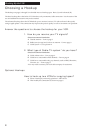
Hooking Up the VCR
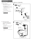
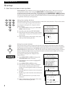
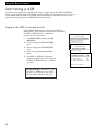
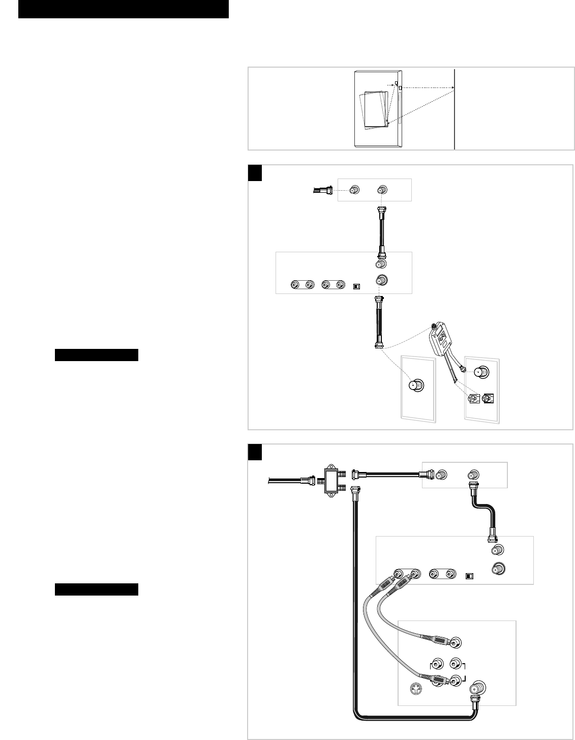
Cable System With Cable Box to Unscramble Pay Channels
(such as HBO, Showtime, Pay-Per-View, etc.)
OUTIN
Cable Box
From Cable
RF Coaxial
Cable
f
Back of VCR
Cable/
Antenna
VHF
UHF
OR
RF Coaxial Cable
(supplied)
75 to 75/300 Ohm
Separator
IN FROM
ANTENNA
OUT TO TV
CH
3 4
INPUT
AUDIO VIDEO
OUTPUT
AUDIO VIDEO
OUTIN
Cable Box
Back of TV
From Cable
RF Coaxial
Cable
(supplied)
S-VIDEO
AUDIO
CABLE /
ANTENNA
L /
MONO
RIGHT
VIDEO
INPUT
INOUT
Back of VCR
Audio/Video Cables
Signal
Splitter
IN FROM
ANTENNA
OUT TO TV
CH
3 4
INPUT
AUDIO VIDEO
OUTPUT
AUDIO VIDEO
RF Coaxial
Cable
RF Coaxial
Cable
Position Cable Box
Position a remote-controllable cable box on
top of the VCR as shown. Be sure not to
block any of the VCR’s ventilation holes.
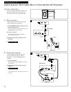
A. Basic hookup.
Use this hookup for a simple connection
which requires fewer accessories.
1. Set the CH3 CH4 switch on back of VCR
to either channel 3 or 4.
You will tune the TV to this channel and use the
TV•VCR button to watch the VCR.
2. Connect as shown.
This connection may require additional
accessories not provided.
3. Plug in power cords of VCR, TV, and
cable box.
4.
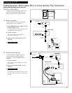
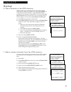
B. Advanced hookup.
Use this hookup for slightly improved
picture quality and more convenient
operation — use of TV•VCR button not
required.
1. Connect as shown.
This connection requires additional accessories
not provided.
2. Plug in power cords of VCR, TV, and
cable box.
3.
You will tune the TV to its video input to watch
the VCR. All pay channels are viewed through
the VCR.
Continue to page 7.
Continue to page 7.
A
B
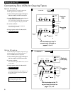
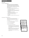
VCR's Signals
Transmitters
Front of VCR
Wall
Cable
Box