


System Overview
D-73d Series Installation/Operation Manual 13
PRE
L
IMINAR
Y
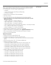
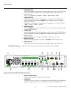
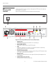
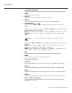
3. USB
A standard, USB Series “B” connection to a personal computer, for performing
software upgrades and other service procedures.
4. RS-232 (To Accessory Box)
A male, 9-pin D-sub connector for interfacing with the Secondary DHD Controller.
(Use a “null-modem” serial cable for this connection.
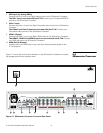
5. Display Control
Connect this to the RS-232 input on the left-eye (top) optical engine on the D-73d
projector.
6. IR
Wired input from a Niles- or Xantech-compatible, infrared (IR) repeater system. It is a
3.5-mm, mini phono jack, wired as follows:
Ring = No connection
Tip = IR Input
Sleeve = Ground
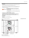
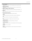
7. POWER INPUT (100 to 240 VAC)
Connect the DHD Controller to power here.
8. HD2 Input (5 x Analog BNCs)
Connect the HD 2 input to the Left Analog output on the 3Dimension Processor.
The HD 1 input is not used with the D-73d. Connect your Component/RGBHV
sources to the 3Dimension Processor.
9. Video 1 Input (RCA)
Connect the Video 1 input to the Left Composite video output on the 3Dimension
Processor.
The Video 2 and Video 3 inputs are not used with the D-73d. Connect your
Composite video sources to the 3Dimension Processor.
10. HDMI 1 Input (Digital)
Connect the HDMI 1 input to the Left HDMI output on the 3Dimension Processor.
The HDMI 2, HDMI 3 and HDMI 4 inputs are not used with the D-73d. Connect
your HDMI sources to the 3Dimension Processor.
11. Ethernet
A female RJ-45 connector for wired network communications.
12. HDMI Out (Audio Only)
Connect this output to an audio control system to pass through HDMI audio.
13. HDMI Out (To Display)
Connect this to the HDMI input on the “left eye” (top) optical engine on the D-73d
projector.
14. RS-232 (PC / Control)
A female, 9-pin D-sub connector for interfacing with a PC or automation/control
system.
The DHD Controller does not transmit HDMI CEC control
messages from the “HDMI Audio Out” connector.
Note