


English
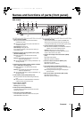
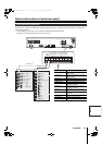
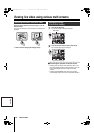
Names and functions of parts (rear panel)
11 Foreword
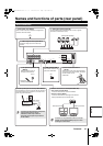
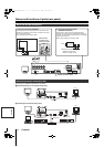
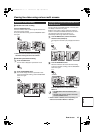
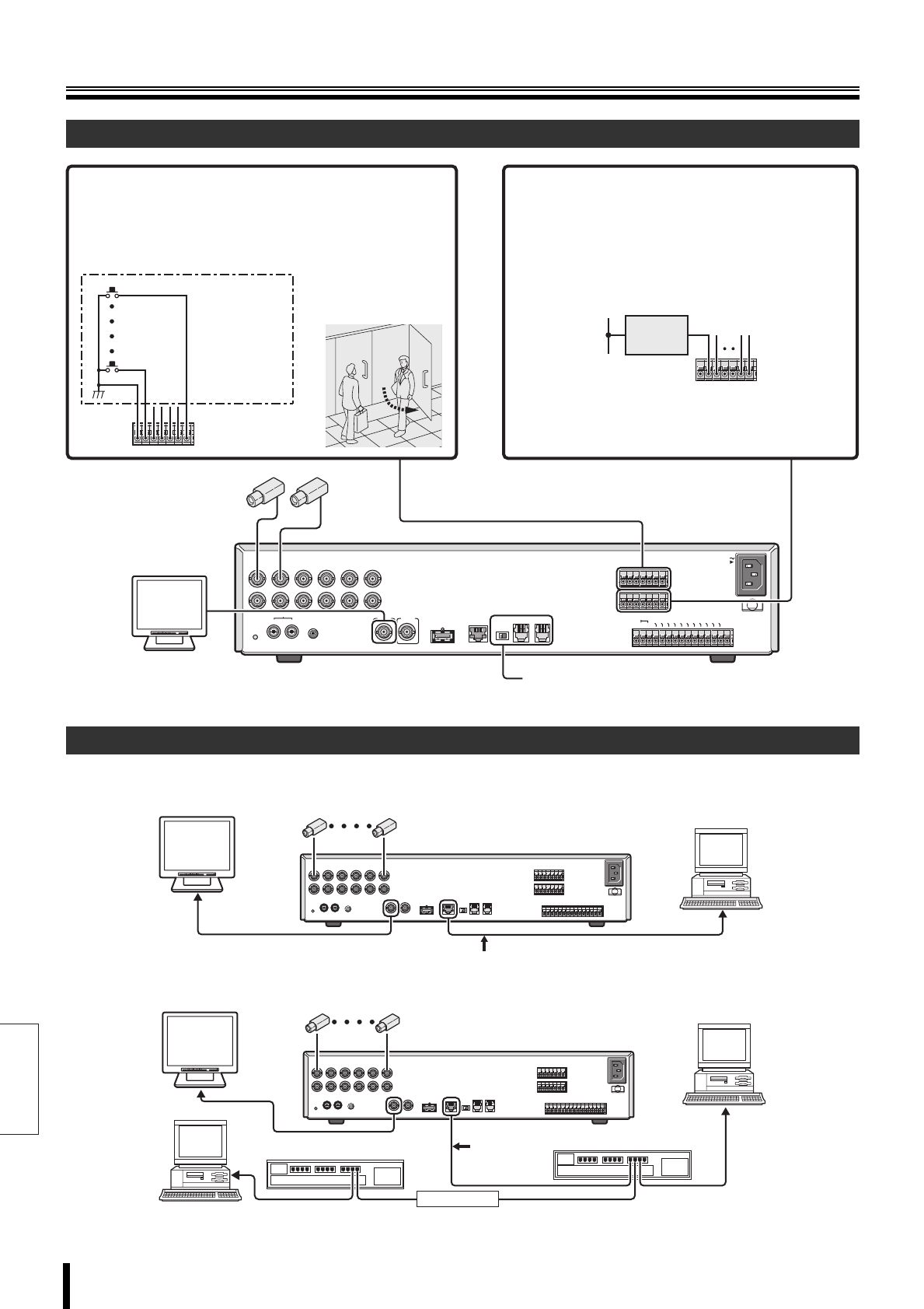
Use Category 5 10BASE-T/100BASE-TX LAN cables.
A Connecting directly to a PC (without using a hub)
B Connecting to the intranet (using a hub)
Alarm and RS-485 connections
Network connection terminals (LAN)
USB
LAN
TERMINATE
RS-485
OFF ON
A RS-485 B
ALARM IN
AC IN
SENSOR
ALARM OUT
C
C
L
O
C
K
IN
C
L
O
C
K
O
U
T
ALARM OUT
ALARM RESET
ALARM FULL
NON REC OUT
WARNING OUT
FULL
SERIES OUT
EXIT TIMER IN
SERIES IN
REMOTE
CONTROL
C
123456
C
123456
CR1R2
1
IN
OUT
ALL
RESET
AUDIO
MON2
MIC IN
IN OUT
23456
MAIN
POWERMODEAUTOMENU
1
6
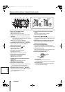
1 Alarm input terminals (ALARM IN)
Connecting a switch or security sensor etc. to the terminal of the
DVR allows the detection of the intrusion of outsiders when doors
etc. are opened and closed.
Alarm input settings are necessary. (P55)
External switch
connected to the
alarm input terminal
2 Sensor alarm output terminals
(SENSOR ALARM OUT)
This terminal is used to output the signals listed below
whenever the motion sensor of the digital video recorder is
triggered. This output terminal can be used for a warning light
by connecting a lamp to it.
Motion sensor settings are necessary. (P58)
Rating for each terminal:
• Maximum current: 25mA
• Maximum voltage: DC 25V
RS-485 connection (P70)
Power
POWERMODEAUTOMENU
1 – 6
Cross type
PC
POWERMODEAUTOMENU
1 – 6
PC
PC
Switching hub
Switching hub
Intranet
Straight type
L8HBM_XE(HARD)(GB).book 11 ページ 2006年2月6日 月曜日 午前10時52分