Page 8
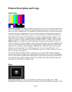
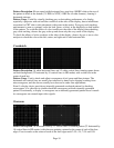
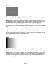
at black (7.5 IRE for NTSC, 0 IRE for other formats) and has a five-step gray scale positioned on
it. The second rectangular zone from the center alternates between two light levels, black and
slightly blacker than black (7.5/0 IRE for NTSC, 0/-4 IRE for other formats). The third
rectangular zone from the center is fixed at a light level slightly whiter than black (10 IRE). The
fourth, outer rectangular zone is fixed at black. The average picture level (APL) of this pattern is
very low.
Pattern Usage: Use this pattern to check the DC restoration (black clamping) performance of a
display device and to set the picture black level with a low APL pattern.
A display device with less than perfect DC restoration will exhibit alternating changes of
brightness in the outer two rectangular zones, due to the display’s inability to perfectly clamp
black to a fixed level. This can be seen especially well with the brightness (black level) control
adjusted to a slightly higher than normal setting. If the brightness level of the outer two
rectangular zones remain constant as the second zone from the center alternates between black
and blacker than black, the display has good DC restoration.
If a display has good DC restoration, its brightness (black level) control can be adjusted on either
a low APL or high APL pattern, with no change in black level as you switch from one pattern to
another. In that case, this pattern makes it very easy to accurately adjust the brightness control.
With the brightness (black level) control first adjusted to a slightly higher than normal setting,
reduce the brightness control setting until the brightness alternations in the second rectangular
zone from the center are just no longer visible. The third rectangular zone from the center should
still be visible as slightly whiter than black.
If a display device has less than perfect DC restoration, you will need to decide, based on the
primary use of the display, whether the black level should be adjusted on a pattern with low APL
or high APL. If the display will usually be viewed in a darkened room, adjust the brightness
control with a low APL pattern, such as this Pluge pattern. If the display will usually be viewed
in a bright room, adjust the brightness control with the pluge levels in a medium or high APL
pattern, such as the SMPTE Bar pattern or one of the Window patterns set to a high IRE level.
Needle
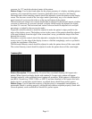
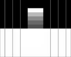
Pattern Description: This pattern is black on top and white on bottom with lines (needle pulses)
drawn from top to bottom on each side of the pattern, through the black/white transition.
Electrically, the needle pulse lines are the same width on the top and the bottom of the pattern. A
five-step gray scale is positioned on the center of the upper black pattern area. The top gray scale
block is 100% white.
Pattern Usage: This pattern makes it easy to detect whether scan velocity modulation (SVM) is
enabled on a display device. If SVM is enabled, the black lines on the bottom of the pattern will
be thicker than the white lines on the top of the pattern. It is also a good pattern for properly
adjusting the contrast/picture/white level control for maximum white luminance level. If the


